

Project Overview
The eternal question ‘Why would you want to write your own game engine’. The answer is very simple ‘I wanted to’. So now that that’s settled let’s move on to the actual contents. This section is more about me and my programming mindset than the tech.
Why Talk About It
I’ve put a lot of work into this project and learned a lot. I guess I wanted to give back, and provide a resource of my own. This is not a tutorial or a how-to. This is my personal stab at implementing a game. Also it will hopefully be more palatable to recruiters than raw source code.
Note there’s no GitHub link to the project. It’s not publicly available and frankly I am just not convinced that it should be. I might Open Source it at some point in the future but no promises.
The project is currently over 50’000 lines of code spread over 400 files.
What is This Project
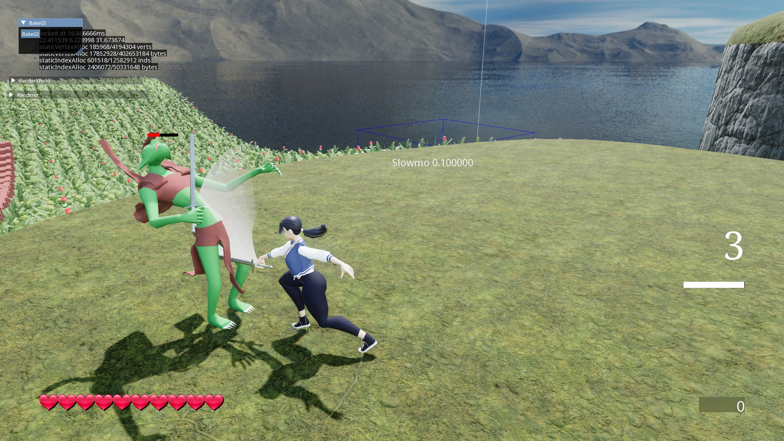
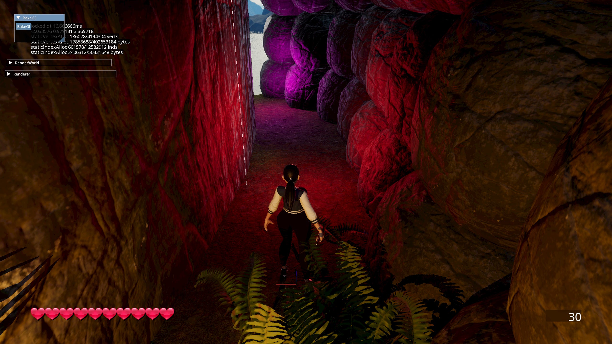
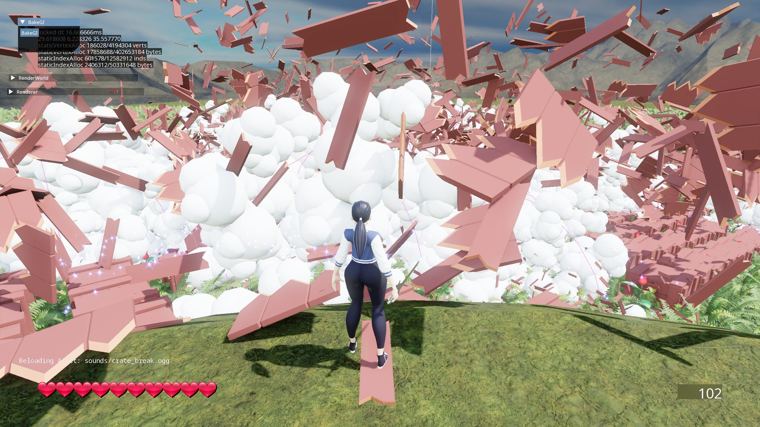
This project is an attempt at writing a game, from scratch while learning and implementing as much stuff that I find cool or interesting. And of course hopefully end up with something other people can play and say ‘This is definitely a game’. As to the design side of things… I’m pretty much just freestyling here.
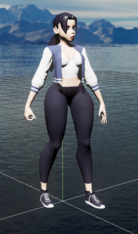
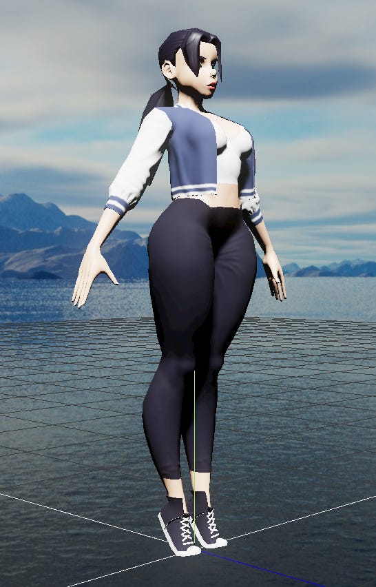
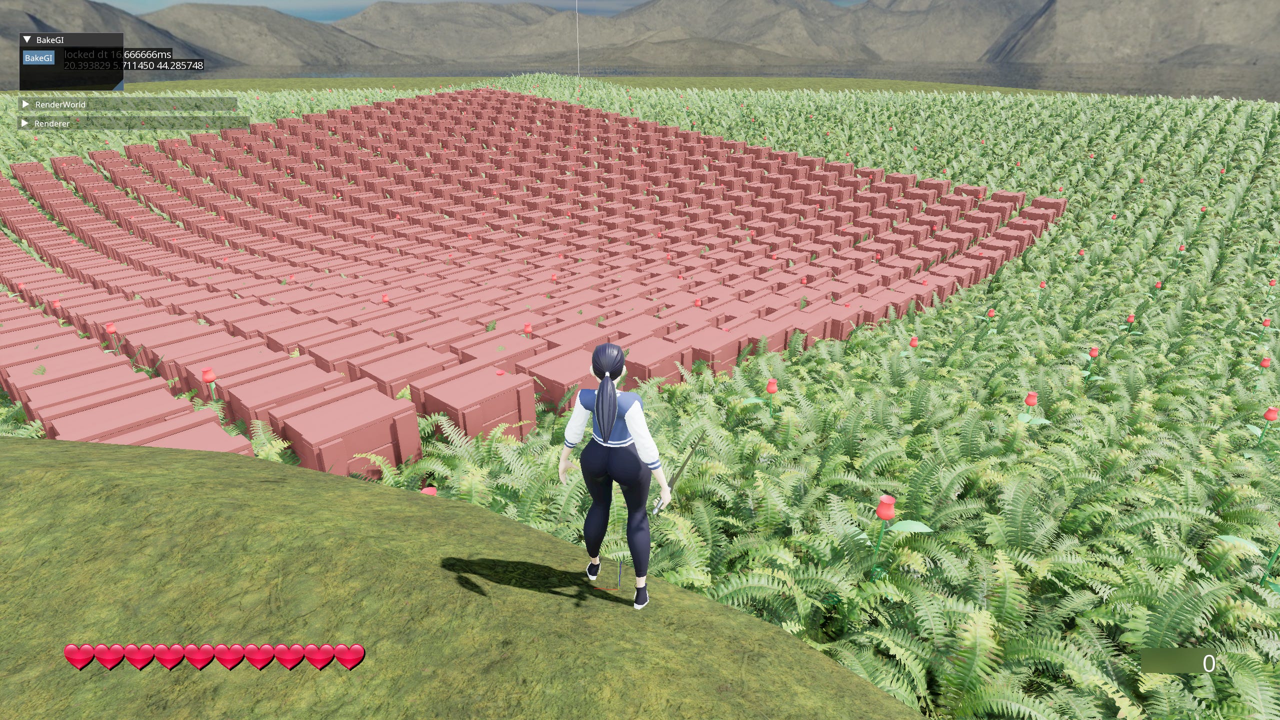
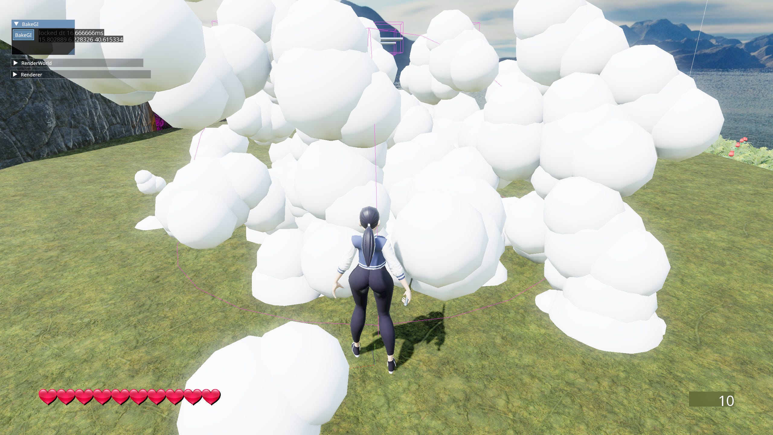
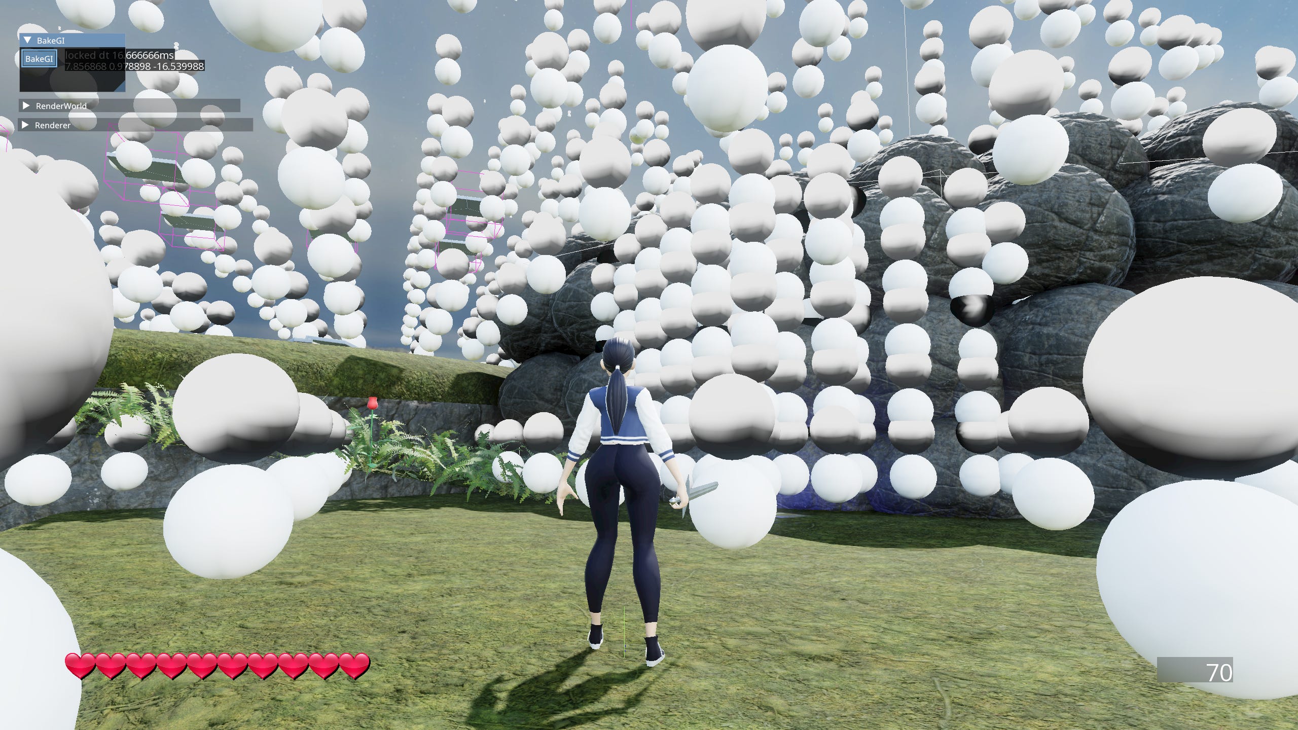
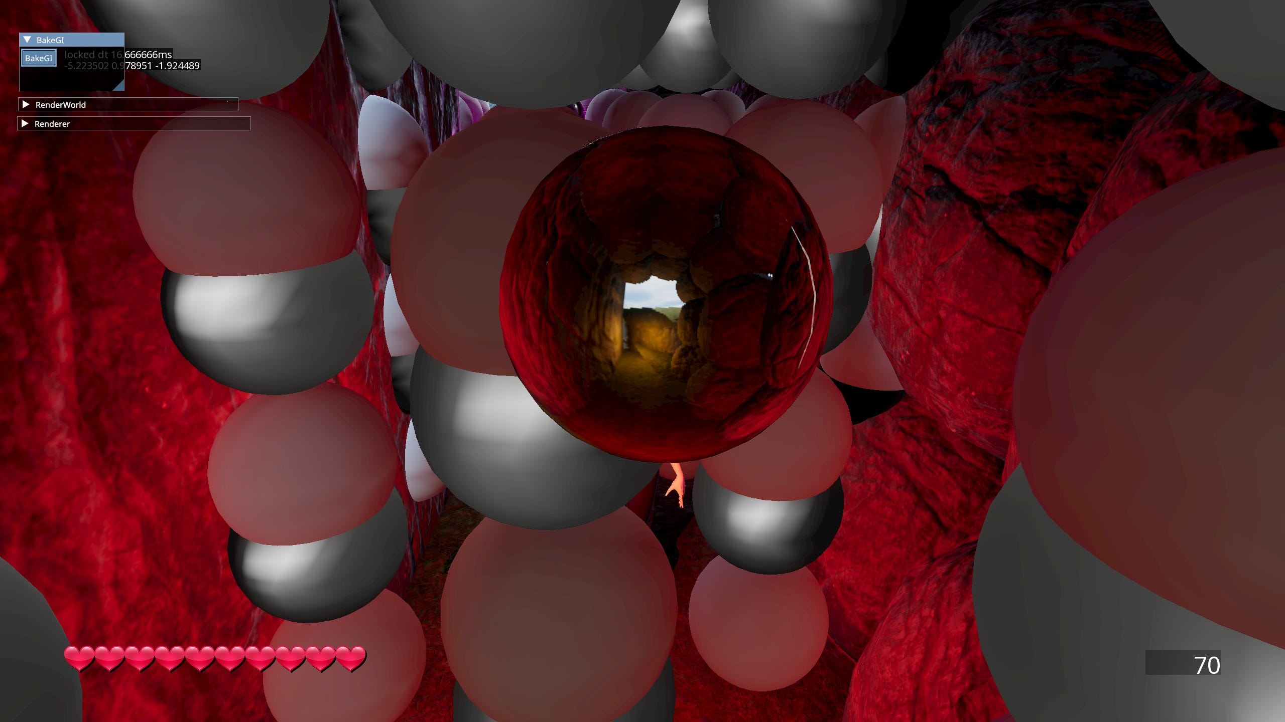
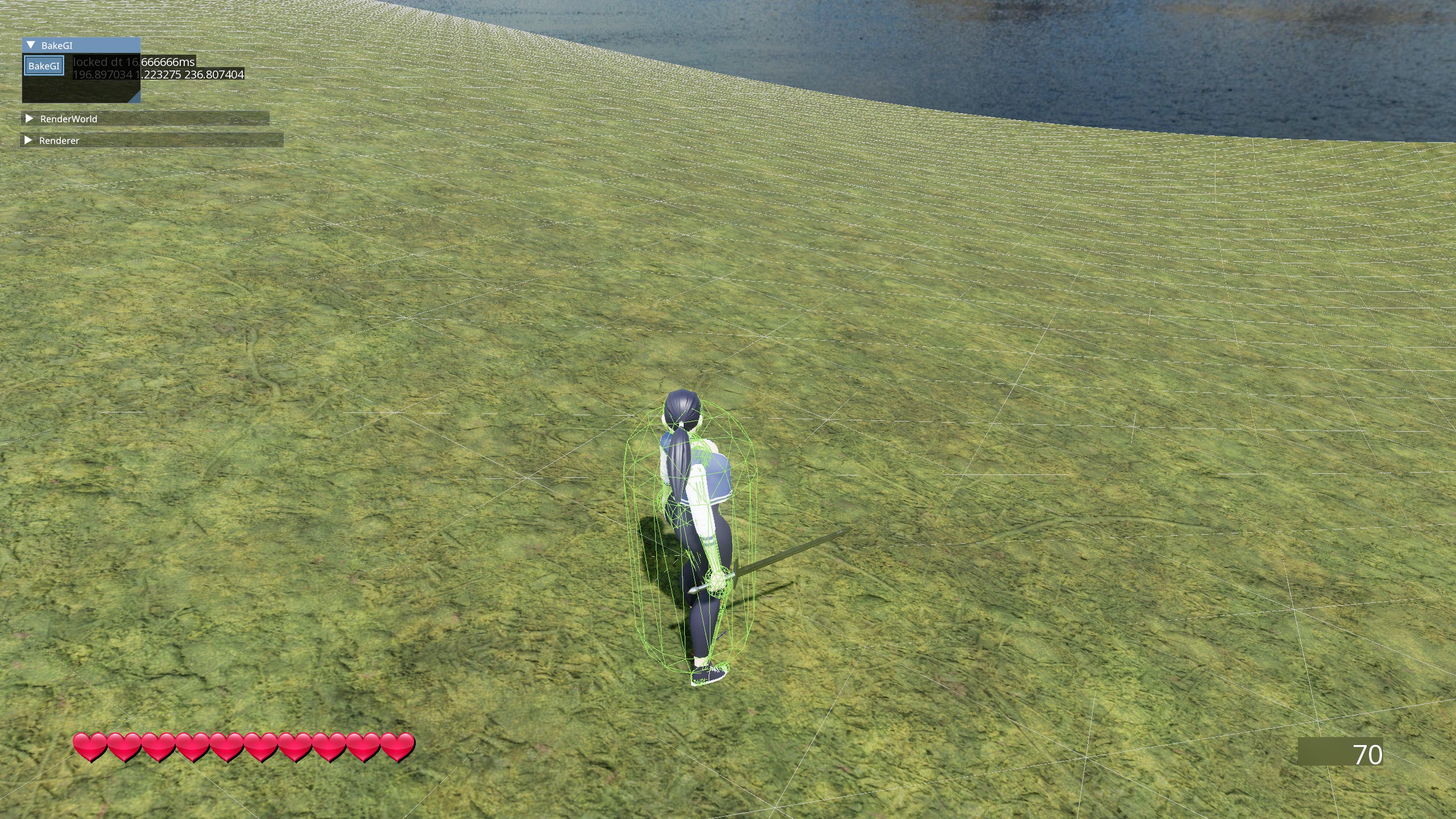
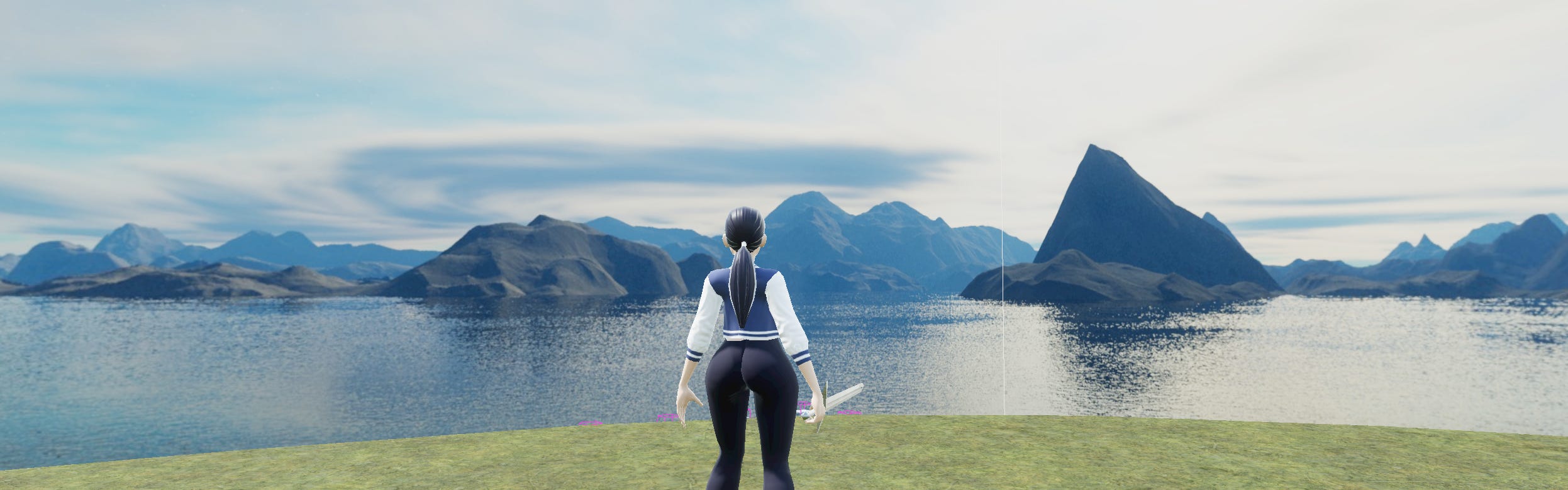
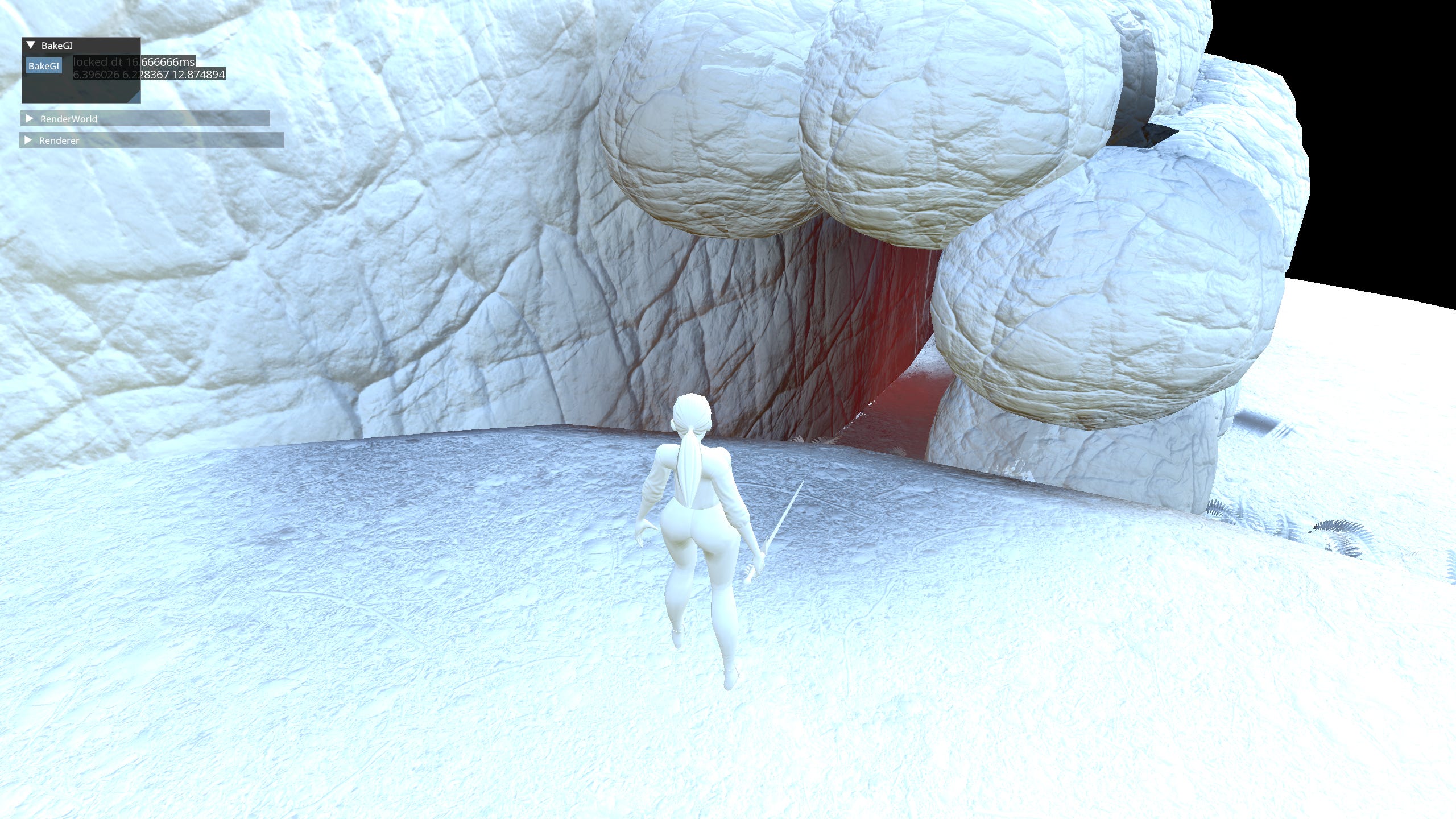
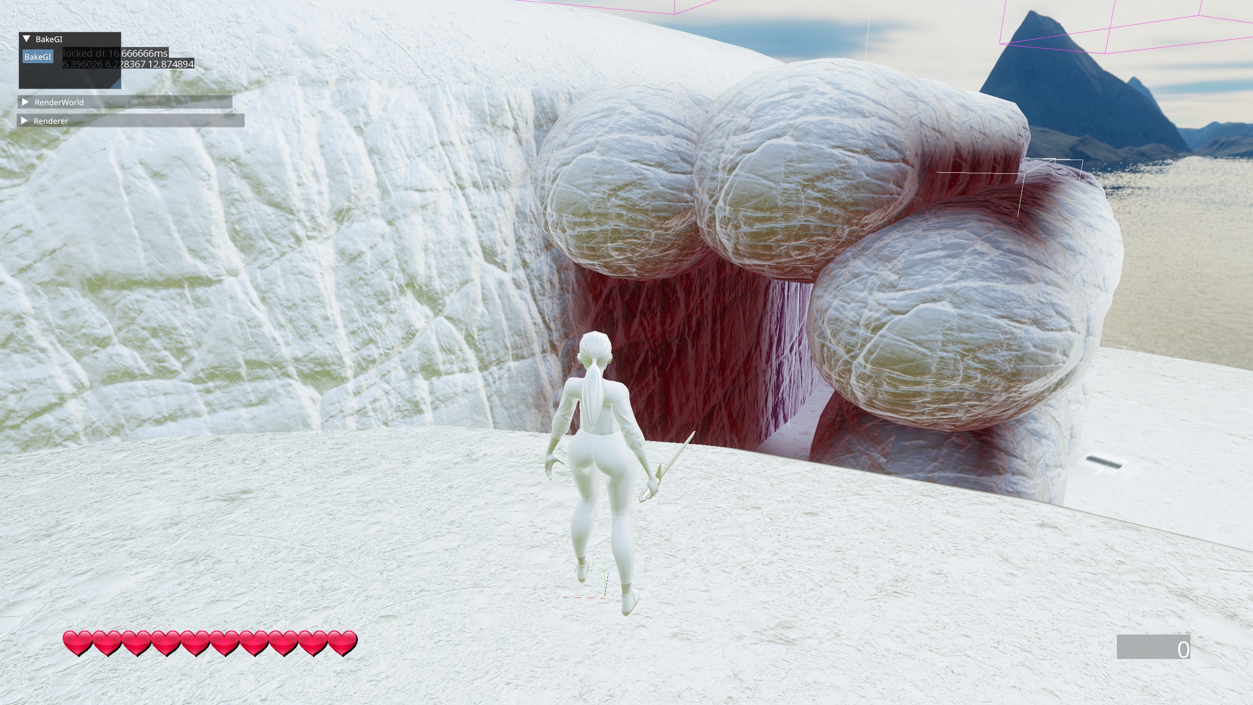
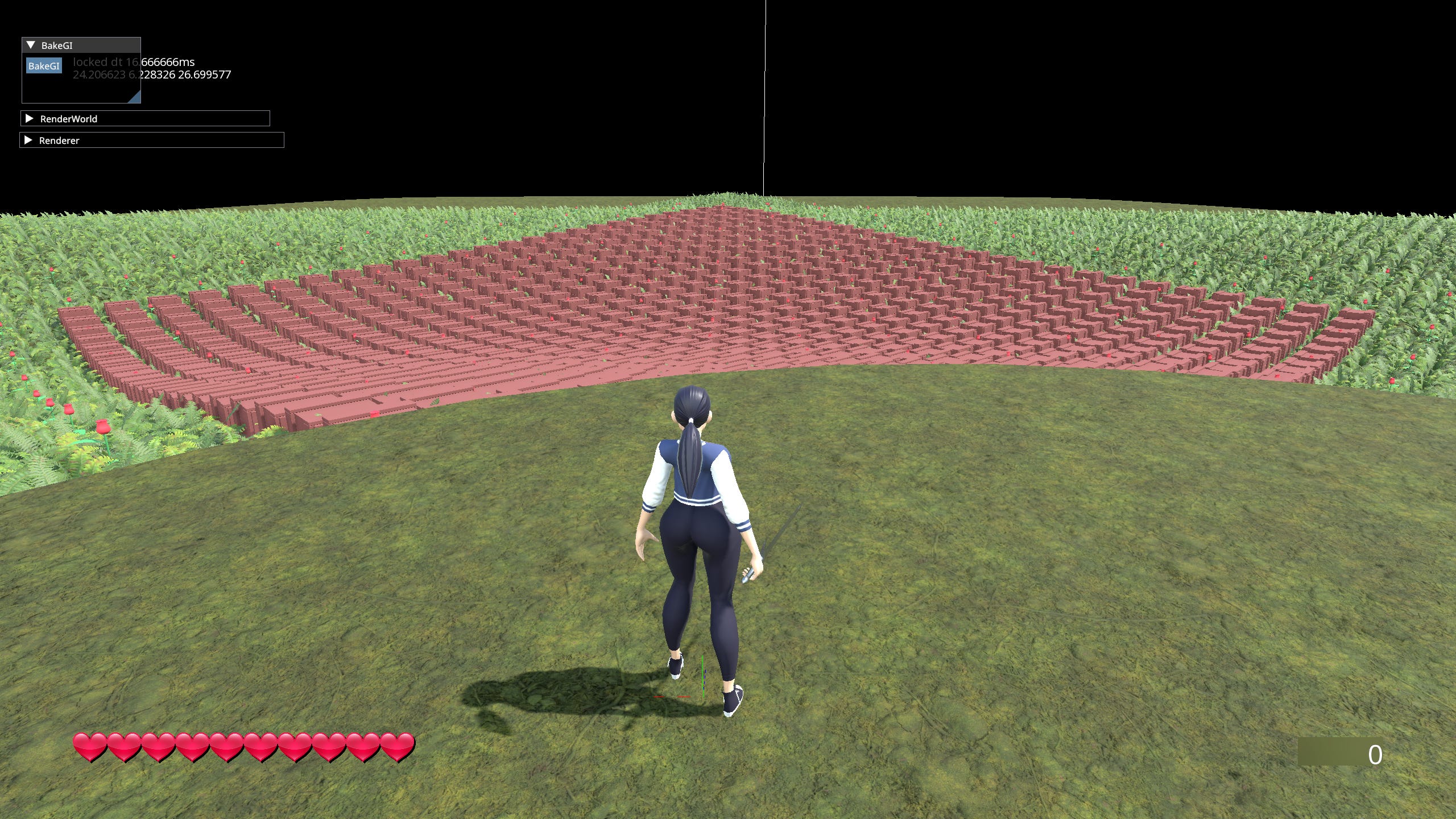
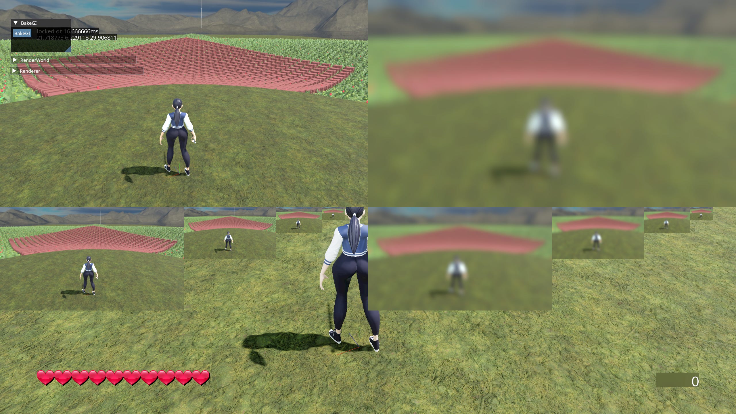
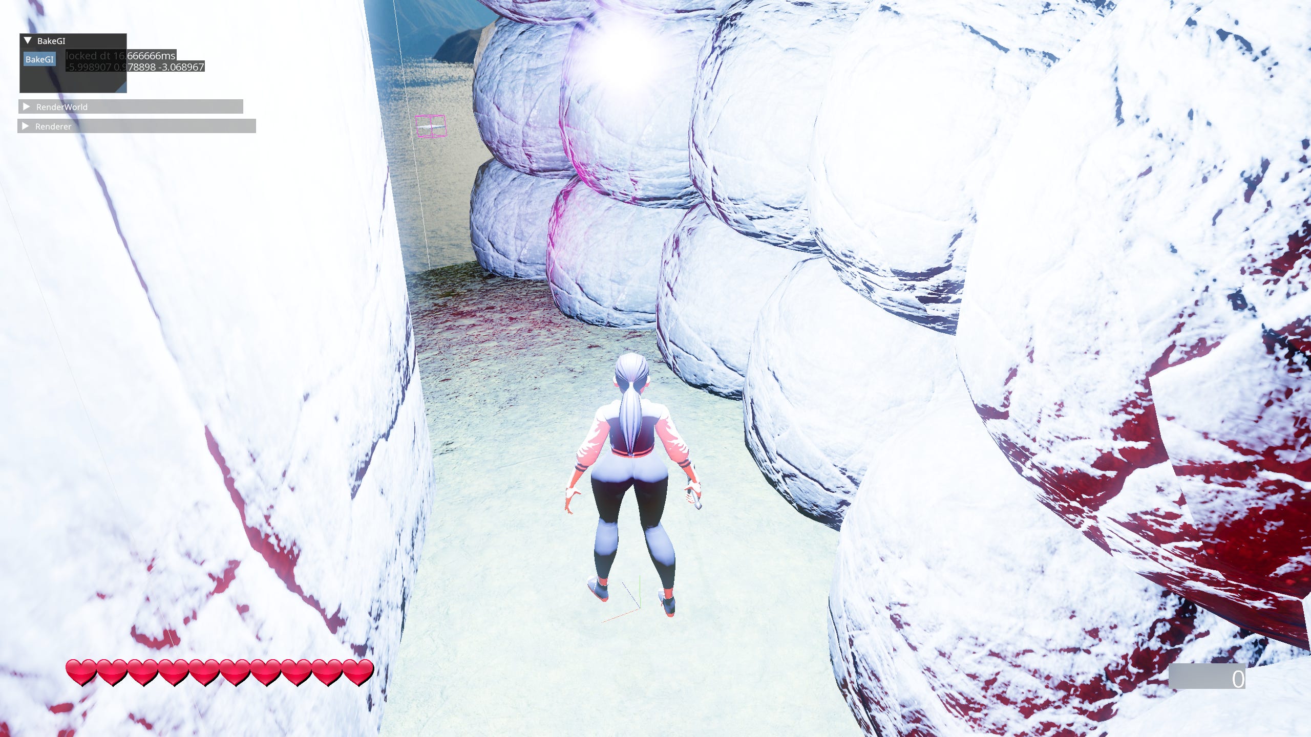
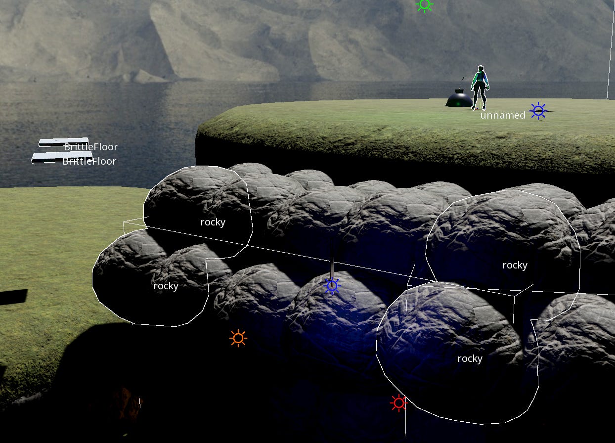
Example screenshots to get the idea across:
Philosophy
There are a few core pillars I try to stick to when working on the project.
Minimalism - I hate bloat, both as a programmer having to look at unnecessary code and as a user having to put up with slow software.
The Handmade Way - The project is written by me, by hand with relatively minimal use of dependencies and no use of LLMs. Contrary to popular belief your software can be smaller, simpler, faster, more robust and more maintainable all at once.
Semantic Compression - Abstraction is a very popular word in programming discourse. Unfortunately it’s not very precise nor useful in general. I prefer to think about compression. Removing duplicated code to make it easier on me a mortal human to deal with. It’s not about hiding low-level details It’s about lightening mental overhead and increasing efficiency of the programmer.
Have The Problems First - or rather don’t try to pre-solve problems you don’t have. Don’t try to ‘future proof’ - it’s a fools errand. The only reliable way to know what problems you will encounter in your pursuit is… having done it before.
Solving problems you don't have creates more problems you definitely do.
Mike Acton
The Core
Finally! Enough with the opinions get to the tech! The Core or simply ‘Core’ is a set of basic low-level utilities used all across the game.
Math
Math utility is pretty run of the mill. There’s no magic here just foundations of 3D. I’ve got the classics like Vec2, Vec3, Vec4, Mat4 & Quat. Operations on them and between them. The math ‘library’ is based on Raymath. It’s changed quite significantly and it’s just barely recognizable.
In general it follows the conventions of GLSL. Including but not limited to - order of operations, construction, access & naming. If you want to know how to achieve a specific result, just think ‘How would I do it in GLSL’.
There are also a couple of neat things like easings, lerps & conversions. One of my favorites is this little guy:

It creates direction vectors uniformly covering the surface of a sphere. I stole borrowed it from the DDGI paper.
Memory
Probably one of if not the most important things you’ll be worrying about is memory. The universal shared resource. There’s never enough of it and the access is never fast enough. How do we deal with that? Here are a couple of things.
Wrapping Malloc - First and foremost, before you do anything wrap malloc & free in your own functions. It might not be immediately useful to you but doing it later can be an incredible pain in the ass. This will become crucial as soon as you want to track your allocations - when (not if) you do, it’s right here taken care of.
Wrap it before you tap it - a common memory management proverb
Custom Allocators
Why do games use custom allocators? Is malloc bad? Short answer - yes. Long answer - yeeeessss. Custom allocators are used for 3 reasons. Fragmentation, Speed and Lifetime management.
Fragmentation - Using allocators such as pool or arena allows for zero waste when it comes to memory utilization, chunks of the same size are used and reused. Memory ‘holes’ are just the perfect size to use it for something else. Thus drastically minimizing fragmentation - the bane of game programmers since malloc existed.
Speed - Allocators usually pre-allocate memory on startup or on demand and reuse it from that point on. Meaning the ‘allocations’ happen entirely in user-space. No switch to kernel, no Operating System shenanigans = speed.
That’s where the list often ends for most games, but I have to mention that last one.
Lifetime management - Instead of calling malloc on every single member and array, having to call free on every single one again. You can just nuke the entire object. No dynamic discovery of just how much there is to free. No - destructor calls unique_ptr that frees that calls destructor that frees and so on and so forth forever and ever. It’s so much faster and simpler, I’m embarrassed I’ve ever used std::unique_ptr in the first place.
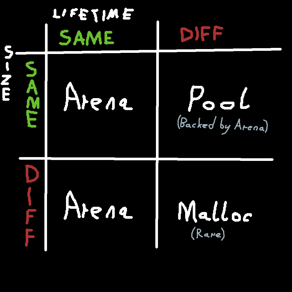
Rule of thumb when to use which allocation method.
The Allocators
Arena - Also known as Stack Allocator, Scratch Allocator or Linear Allocator. It really is as simple as it sounds - a block of memory with an incrementing integer.
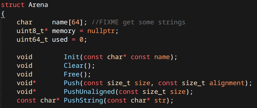
Well that’s as simple as it could be. I went a step further, my arena uses virtual memory. It pre-allocates a big chunk of virtual address space, then when used it requests new physical memory pages to be committed as they are used. This results in an effectively ‘infinitely’ growing allocation. All pointers to memory arena are stable, only invalidated if the arena has been freed or ‘popped’.
Many types request an arena to allocate their internals, many types have internal arenas within them. This ensures that a type’s ‘guts’ can all be allocated & freed together. As well as be close in memory for nicer faster access. This renders techniques such as std::unique_ptr useless.
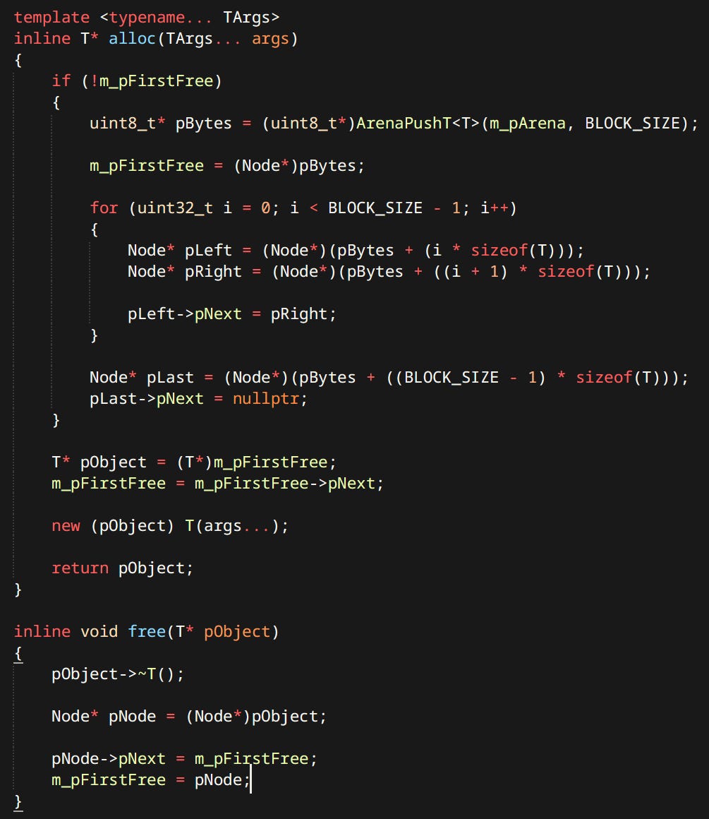
Pool Allocator - Also known under the moniker Object Pool, Bucket Allocator, Slab Allocator or Small Size Allocator. My Pool Allocator is a linked list of ‘Slots’ of a certain size. When allocation happens it simply pops the head of linked list and returns the slot. When freeing happens it does the reverse and pushes a new head. When it runs out of space it allocates a predefined amount of new slots from the backing Arena. Making it effectively infinitely growing as well.
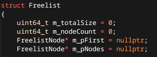
Freelist - Not sure about a good name for this one. Sometimes called a Dynamic Allocator. It’s a doubly linked list of nodes, each node containing it’s size and whether it’s used. Upon free the nodes consolidate into bigger nodes. This one is different than the others. Specifically it doesn’t have any memory, just the metadata. It’s used to dynamically allocate external resources that are not necessarily bytes e.g. sections of a vertex buffer.
RTTI
I know C++ has some form of RTTI built in… I don’t care. I have a very simple custom system. stolen from Jolt wholesale An individual type is represented by a few simple members.
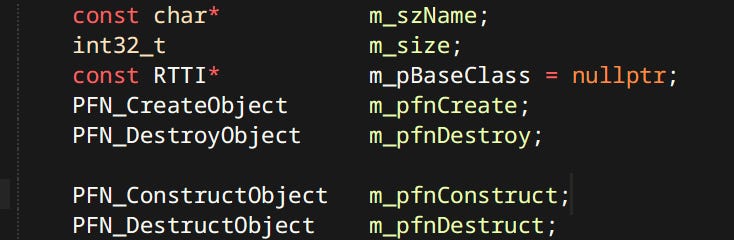
The fields here are pretty self explanatory. Create & Destroy are basically new & delete. Whereas Construct & Destruct are placement new & calling the destructor combo.
Types are stored in the TypeRegistry:
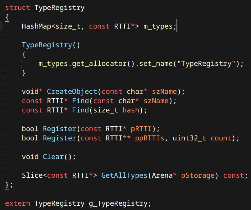
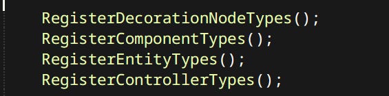
Types have to be registered in the TypeRegistry manually.
With just that I can trivially get the type of an instance, serialize it’s name, then say ‘make me one of those'.
This could be improved by adding some way to handle members of the type. Possibly allowing automatic serialization but that’s something I haven’t yet delved into.
Threading
Threading is done in a very simple and noob friendly way - through a Job System.
Every system can just go wide when it needs to, do the work, then join. There’s very little room to screw this up. Unlike in other cooler job systems.
Note on use of STL
The standard template library is used in the project… or rather it’s third party implementation: EASTL. Why use a different version of STL than what comes with the compiler. There are good reasons for it.
The Masquerade - Well for one, using regular STL is not using a library since it’s actually multiple libraries that pretend to be one. Depending on your compiler & target the implementation of STL will be different. With a cross-platform choice like EASTL you get the same thing everywhere. That gives you control. When I say:
vector.set_capacity(0); I know for a fact the container will free it’s memory. (STL can’t do this btw)
Code written by humans with eyes - Code for EASTL can be read. It just looks like normal code. That about infinitely more than you can say for your common STLs.
Allocators that work - In regular STL allocators for containers are templated on the type stored by the container. Which is borderline braindead. With this restriction they’re virtually useless for anything more than wrapping malloc. In EASTL allocators are first class citizens that have instances, can be accessed and changed. You can actually use an instance of one allocator in as many containers as you want! Crazy I know!

Written specifically for games - It’s written with performance in mind. Not ‘safety’. Not ‘correctness’. SPEED!!!
Can do ‘unsafe’ things - It understands that it’s being used with allocators and what that implies. It has things such as reset_lose_memory(). It’s a call that simply orphans the internal memory and resets containers’s state. You call it when you know that the allocator will do the freeing and destructor calls are not necessary.
JSON & Mason
I have custom JSON-like called Mason (Get it? It sounds like JSON but is a real word!). It’s syntax is slightly different and more human friendly for writing files by hand. For new systems Mason is used but there’s a lot of legacy JSON stuff. For all intents and purposes they should be considered equivalent.
So when you see one or the other used it’s just legacy.
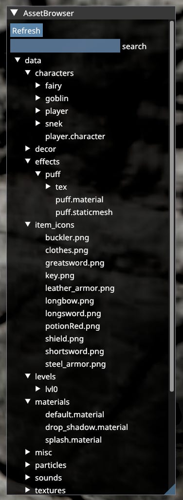
Asset Pipeline
I was wondering where to start talking about something as huge and complex as a 3D game. Following the teachings of Mike Acton I followed the data. Let’s start with The Asset Pipeline aka how do I even get data into the engine? I will use Static Mesh as an example. It’s one of the simpler types but it does show off what matters.
In my engine ‘Asset’ is defined simply as a piece of immutable data read from disk. e.g. a mesh, an animation, etc. Things like the config files, or game saves are not assets since they are expected to be written out by the game.
Asset Description Files
As far as engine is concerned first thing you need to do is create an Asset Description File (henceforth known as ADF). It defines what the asset is, it’s metadata and the source file for the meat.
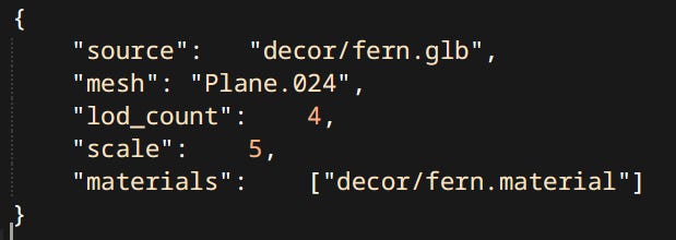
Each asset type has it’s own ADF schema. Here in fern.staticmesh in order:
source - the GLTF 2.0 file containing the actual geometry of the mesh
mesh - since GLTF 2.0 files can store many instances of many types of data. We’re gonna have to be specific about which mesh particularly we want.
lod_count - meshes have levels of detail generated automatically with the use of industry standard library: meshoptimizer. This property dictates how many.
scale - meshes can be scaled on import so it doesn’t have to be done in runtime. It’s mostly for convenience.
materials - which materials should this mesh use. In this case there is only one material slot. fern.material is yet another ADF.
Every asset type has different properties. Some of these are optional others are not.
GLB Import
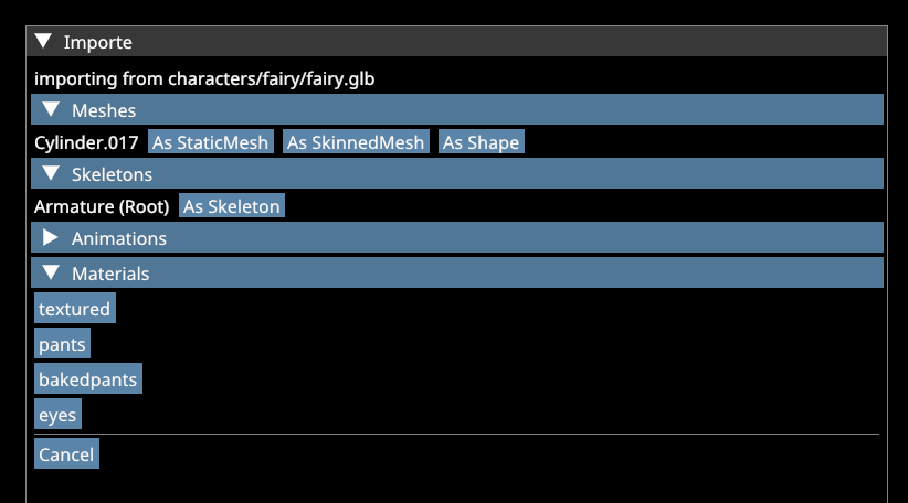
To import a file I just drag & drop it onto the editor. Then a window listing all contents of the file shows up.
When selecting an asset. A section with inputs appears. These are the same data as in ADFs but can also be dragged from Asset Browser.
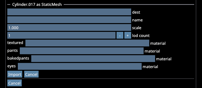
Using the importer is an optional convenience. ADFs can still be written manually.
Compilation
Assets need to be compiled in order to be used by the engine. Not all assets though. As a general rule of thumb asset types endemic to the engine such as AnimGraphs, Prefabs or Materials do not need to be compiled. Since engine writes them already containing the data it needs. Asset types coming from external sources like Meshes, Animations, Skeletons need to be compiled.
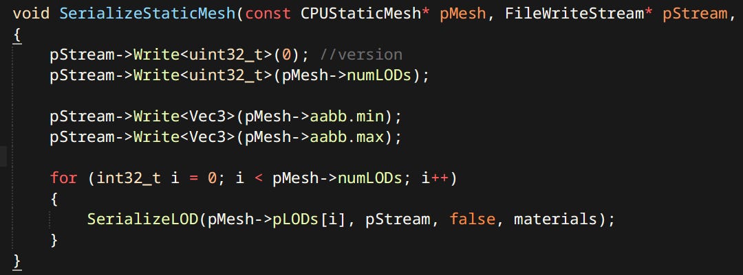
What is Compilation? Also known as Building, Massaging or Conditioning. Is conversion of external data into engine specific formats. Every engine has some form of data compilation somewhere.
In this case the term compilation means ingesting the ADF fetching the source data and creating a runtime representation of the asset. That runtime representation then gets serialized to disk in a compact easily loadable format.
Compiled assets are stored in a cache folder. Their name is the hash of original ADF file path. Every time an ADF is changed the asset is recompiled and the resulting file is overwritten. Very similar system is used by Unity and Godot.
Asset Database & Asset Registry
Asset Database is a directory of all assets present in ‘data’ folder. Whether they are currently loaded or not. It is responsible for detecting changes in ADFs, as well as being utilized by tools.
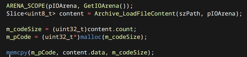
Asset Registry is a container for all currently loaded Assets. At any time the runtime can request an asset like so:

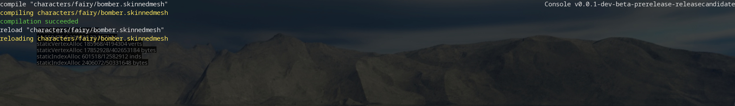
Now the asset is ready to be used by the runtime however it wants. Loaded assets can also be reloaded at runtime. Systems can register a reload callback to recreate runtime data if necessary.
For now there is no asset streaming as it is quite a rabbit hole. I hope to get around to it some time.
Authoring
First off we have to create an asset (or download one). In case of a mesh it’s gonna be with the use of Blender.
Now that we have a nice mesh we need to export it. My engine only deals with GLTF 2.0 files when it comes to all Blenderborne asset types.
Following sections are in no particular order
Debugging
The project contains numerous debugging and data visualization facilities. Quite simple ones but they go a long way.
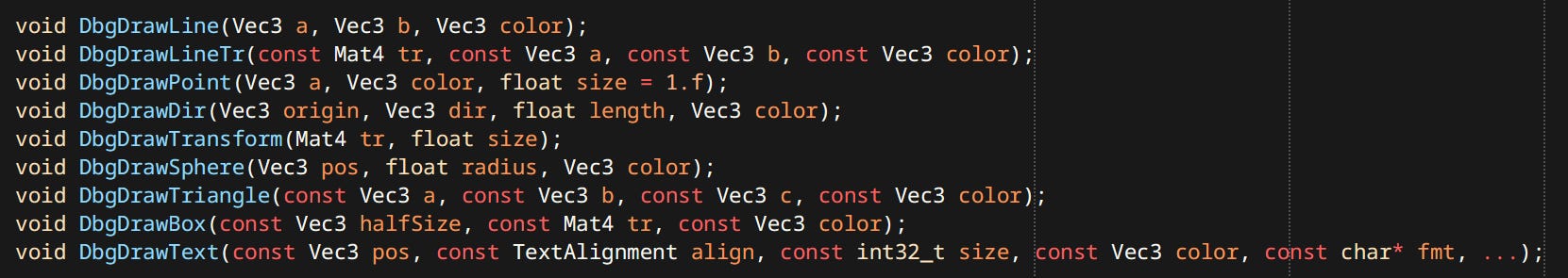
Debug Drawing
Debug drawing is a set of function calls that can be used anywhere anytime even in parallel. The system queues up drawn shapes per thread and flushes them during rendering. A number of different shapes are supported:
Logs
There’s 4 types of logs currently in use across the game.
printf - The single most important, most useful, simplest debugging facility known to mankind.
Stack Log - Shows persistent lines of text in top left corner of the screen. Text only moves when new lines are added or removed. Used for things I want to keep track of consistently like player’s position.
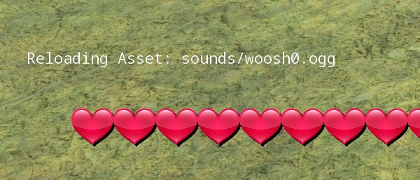
Notify Log - Displays queued up prompts, then after a certain time pops them. Used for things like reloaded assets, interactions performed, etc.
Console Log - Quake style console has a log of it’s own. For messages relating to commands used.
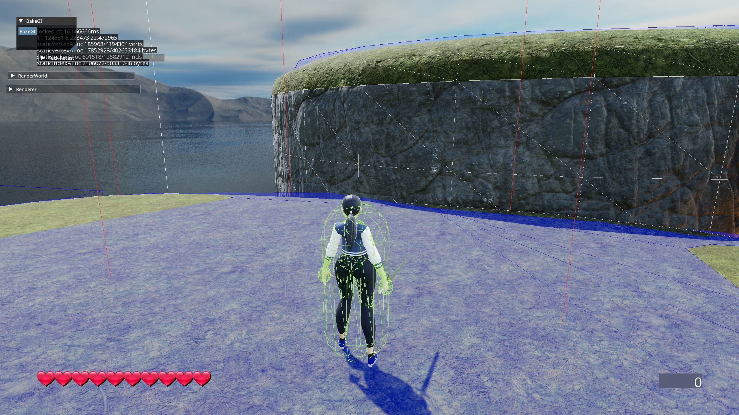
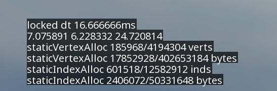
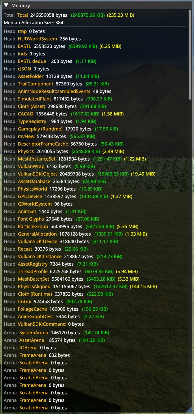
Memory Tracking
Remember when I told you to wrap malloc. This here is why. Memory tracking shows amount of memory used by every heap allocation category, as well as every arena. Undeclared allocations are set as ‘General Allocation’. Tracking can be refined as needed. Arenas are tracked automatically.
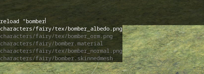
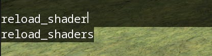
Console
A Quake style console for general engine-wide things like reloading assets, reloading shaders, etc. Each command can define it’s argument types for use with suggestions.
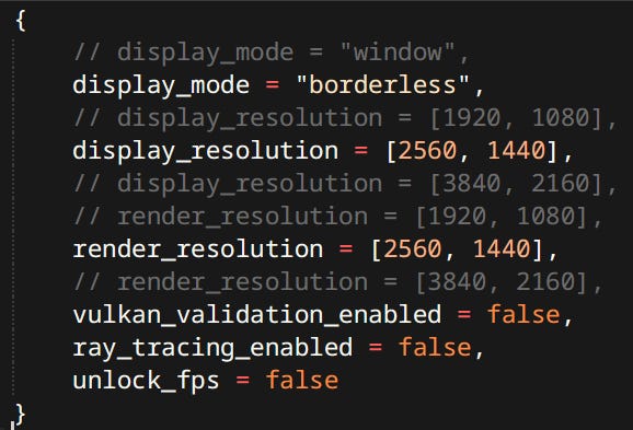
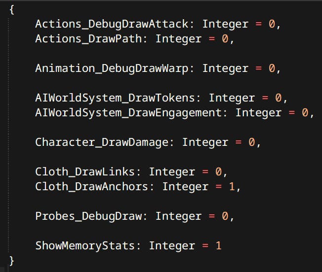
Vars
Vars are similar to Quake’s cvar_t. They are variables saved to a file that can be reloaded in real-time. Used to enable/disable debugging visualizations and other features (like the memory tracking window).
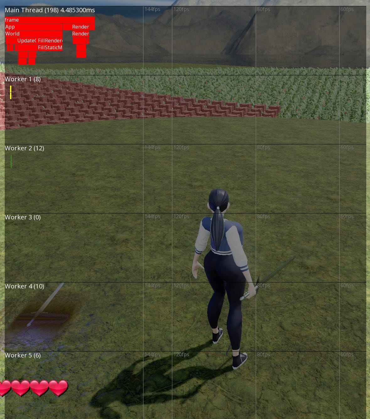
Profiler
The engine is instrumented with profile scopes. Profiling data is gathered to be displayed in game. There also exists Tracy integration for more in-depth analysis.
Animation
Animation is a big subject. Unfortunately not too often discussed. That is sad because I find it one of the most fascinating facets of game development, probably even more so than rendering. My animation system is partially inspired by the one described by Bobby Anguelov.
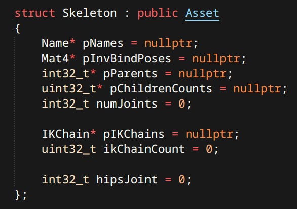
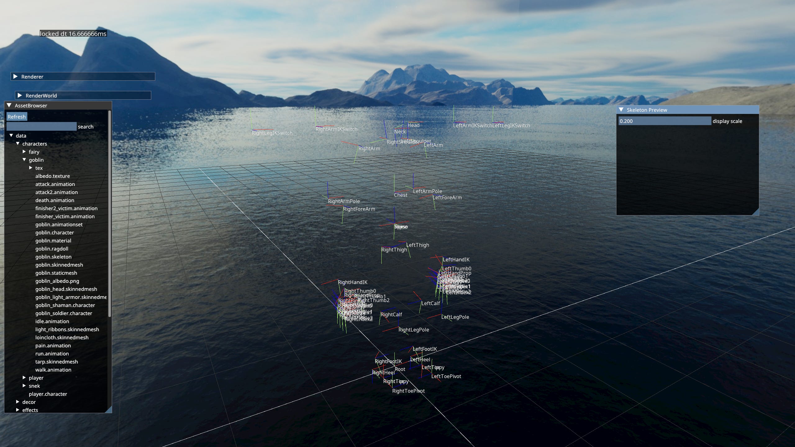
Skeleton
A Hierarchy of Transforms. Individual transforms are often called Joints or Bones. Skeleton’s job is to keep track of relationships between them. As well as storing the inverse bind pose.
Bind Pose - Pose the skeleton was in when a mesh was being bound to it. Inverse Bind Pose is used for skinning.
Additionally there can be other metadata in my case it’s IK Chains and a hip Joint.
Pose
A set of particular joint transforms. Usually sampled from an animation or generated procedurally from Ragdolls.
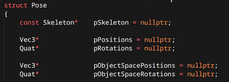
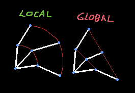
Joint poses are stored both in local and object space. Both are useful in different contexts and can be computed from each other.
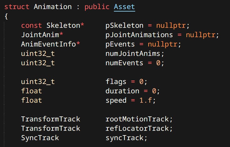
Animation Clip
(often shortened to Animation or Clip) A sequence of Poses stored together with timing information. Animation Clips often contain meta-data like Root Motion, Events or other engine specific constructs. Animations like most 3D things in this project are created in Blender.
Contents of an Animation always include an animated skeleton. Optionally they can also have a ‘Root Motion Node’ and a ‘Reference Locator’. Here’s an example of an animation ADF using many available features:
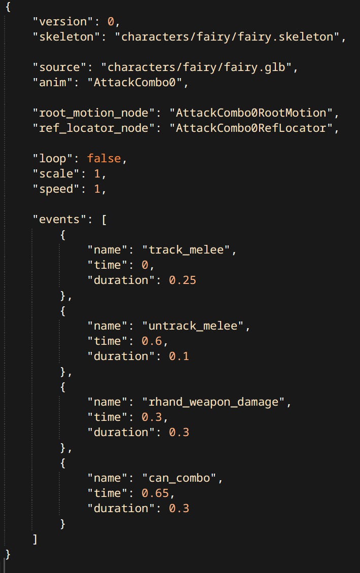
Currently Joint Animations inside a clip are mapped to skeleton joint purely by index. I plan to make them map by name to make animation assets more robust to skeleton changes during character design iterations.
Events
Events are engine specific data on a timeline. Sampled from a clip much like poses. In my case events can either be instantaneous or have a duration. When a duration event is sampled it’s phase is recorded. Gameplay code can query what events have been sampled that frame and act accordingly.
Phase - Point in animation represented as a percentage of the overall duration.
In engines like Godot for example Anim Events are timed function calls with arbitrary side effects. My Anim Graph queues up sampled events in it’s internal state, making it trivial to update in parallel without worrying about side effects.
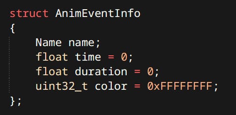

Possible improvement for this system would be to allow multiple different types of events each with it’s own set of members. Currently the only piece of data that events have is their name.
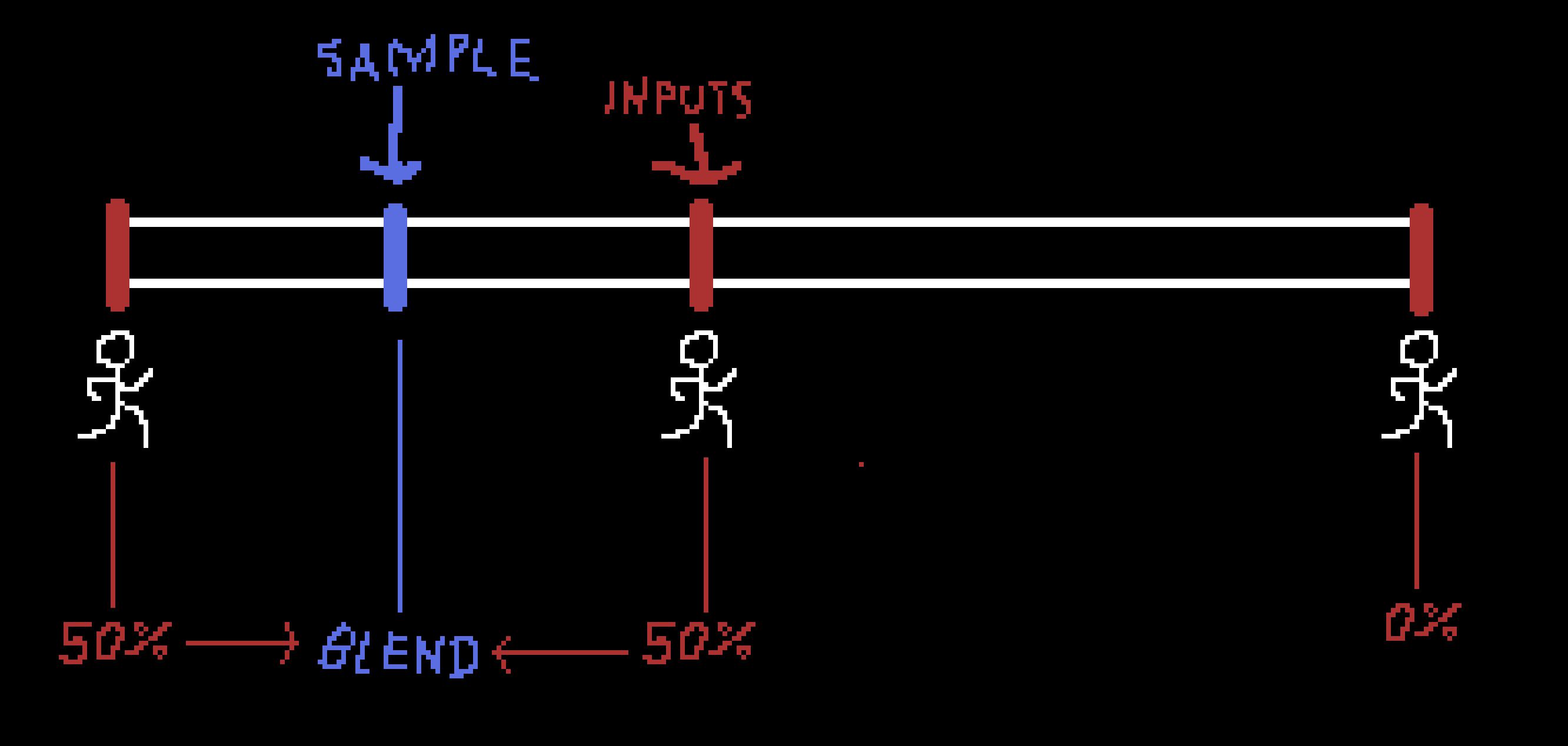
Blending
Blending poses is as simple as interpolating local positions and orientations of joints. It is paramount that local transforms are used, otherwise the overall movement of the skeleton would be incorrect. Blending is used for sampling clips between existing frames or mixing them together.
Syncing
Syncing is achieved through the use of Sync Track. A Sync Track is a set of Sync Events which are a lot like regular events. They split the animation into named sections. When two animations are played together their Sync Tracks are ‘blended’. Event lengths, timestamps & durations are interpolated. If the number of Sync Events is mismatched lowest common multiple is used. During playback the blended sync track drives the speed and phase of participating clips.
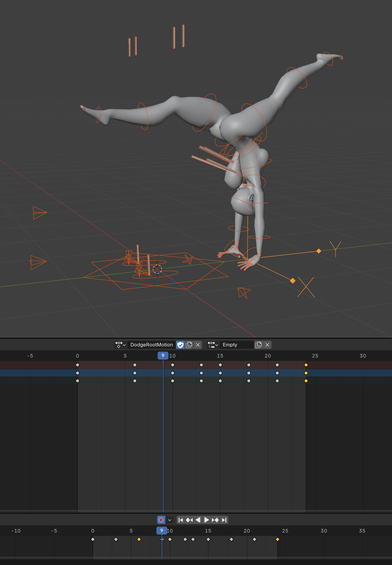
Root Motion
Root motion is the trajectory of the skeleton root. It can be either extracted from the animation or authored by an artist. The purpose of Root Motion is to translate the whole character while taking environment collisions into account. As opposed to simply playing an animation where only the root joint would be moved.
Example of an Animation Clip with Root Motion data:
Example of Root Motion begin used to move the character:
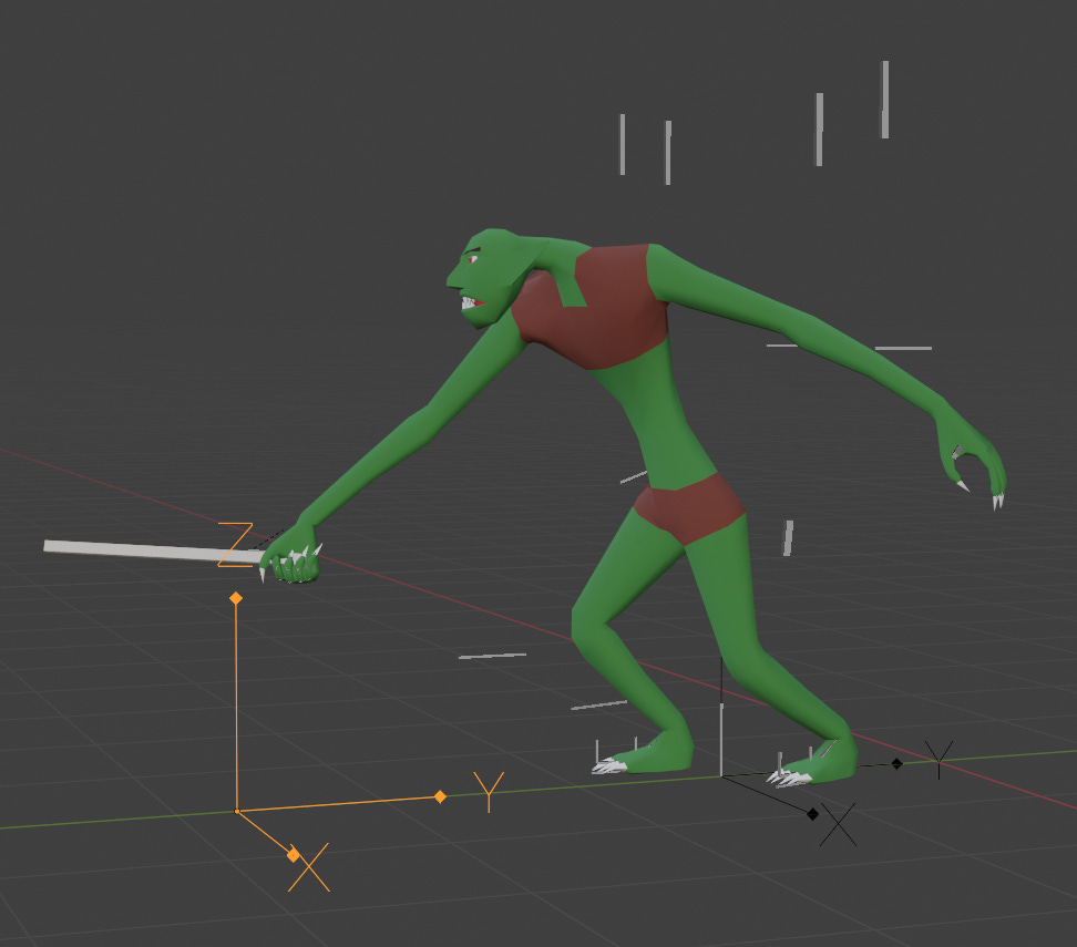
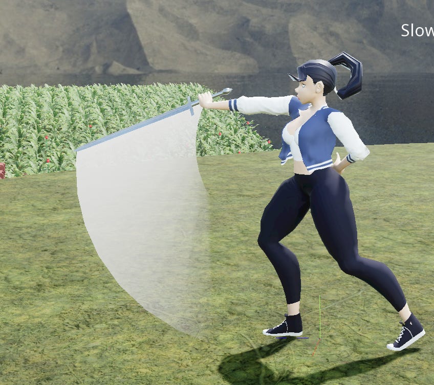
Ref Nodes & Motion Warping
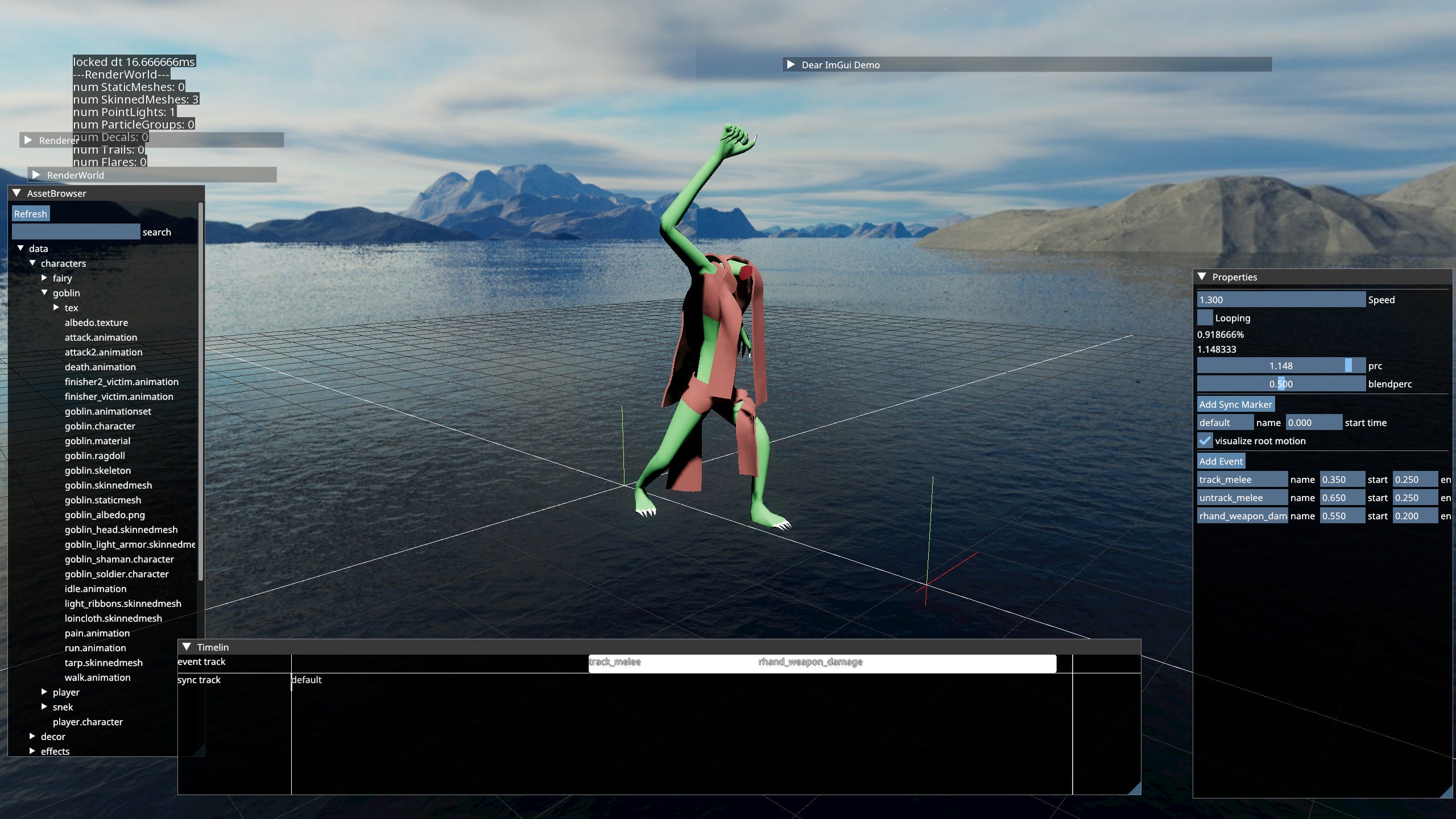
Reference node is a transform stored in an Animation Clip. It's useful for placing the character relative to a point in space. e.g. The selected node in the screenshot is a location where the melee target for attack is expected to be. At runtime the character can warp it’s root motion to match that transform. Warping is a process of modifying the root motion procedurally at runtime. In this case used specifically to match a world space transform with the reference. There exist other kinds of warping as well such as orientation warping, which only rotates the character etc.
A video of two characters using reference locators to align with their melee targets:
Currently full transform warping with reference locator is the only kind of warping my engine supports.
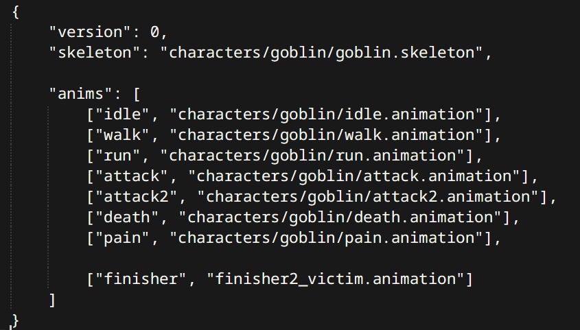
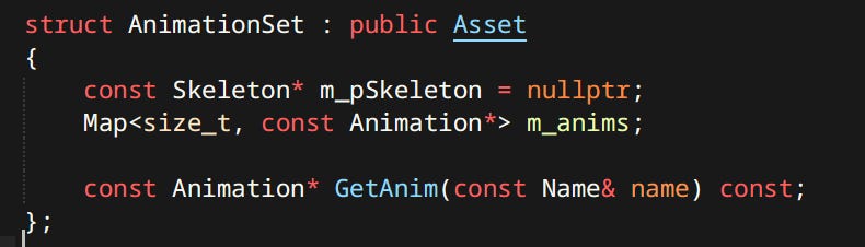
Animation Sets
Animation Set is a mapping between simple names and actual animation assets. It’s primary use is in Anim Graphs. One graph can be used with different sets making it possible to use the same one for different characters.
Inverse Kinematics
IK application for feet involves a couple of steps:
Foot IK becomes activated by animation events.
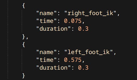
Anim Events controlling IK The system casts rays from animated foot positions downwards. These points are then offset by the elevation of the foot joint aka. the ankle position.
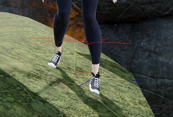
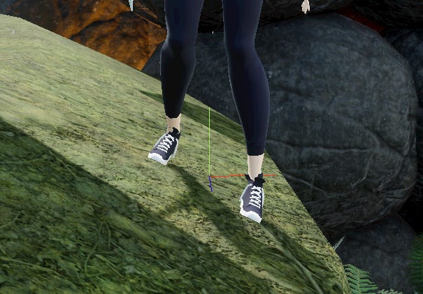
Debug Drawing for Foot IK Hips are pulled downwards based on elevation of the lower hit point, so that both feet touch the ground.
The new positions of the knee joints are computed, and pose is moved to accommodate. Two bone IK can be computed analytically using The Law of Cosines.
Feet are rotated so that their original ‘up’ vector matches the ground normal.


Look Ats
Look at is another procedural adjustment aiming to make the character look in a particular direction. At the moment look ats are hardcoded not a proper part of the animation system.
Look At applied to the spine:
Look At applied to the head:
Additive Poses
Additive pose is a difference between two poses that can be added on top of another.
Example of applying the additive pose on top of currently playing animations:
As of now additive animation is still hacked in, not a proper part of the animation system.
Anim Graph
Anim Graph is the beating heart of the animation system. Everything relating to animation (that is not a hack) happens inside an anim graph. The main components are:
The Layers
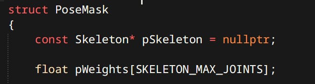
Top level of any anim graph is a stack of layers. Layers can be blended together with a Pose Mask. Pose mask is a structure containing weights per joint. Allowing you to blend upper body animation with lower body animation like reload while running. Interesting part is the masks are not stored per layer but per state. Meaning every state in the layer can have different mask. Masks are also blended during transitions.
Example of upper and lower body playing different animations:
The State Machine
Each layer contains exactly one state machine, which comprises of two main kinds of nodes:
States - Contain blend trees, list of transitions that can happen from this state and their conditions.
Transitions - their main purpose is to switch from one state to another. Secondarily it visually blends between the animations. As soon as a transition is confirmed, logically graph is already in the target state which allows it to travel multiple states without waiting for transitions to finish.
Transitions are the first-class citizens in my implementation of the graph. Gameplay code can request transitions by name:

It does not know or care about what state the graph is currently in. When it requests ‘death’ transition, it only needs to know that somehow a ‘death’ will happen. Requests can also fail and return false if the given transition is not available. The ‘death’ transition is an example of ‘global transition’. Available from every state it cannot fail.
The Blend Trees
Blend Tree is an arbitrary tree of Anim Nodes. Anim Nodes generate and consume poses from other nodes. Examples include:
Clip Anim Node - Samples a pose from an animation.
Blend 1D Node - Takes a spectrum of input poses and their sample points. Finds poses neighboring desired point and their weights. For example there can be one ‘locomotion’ state with samples being 0.0 → idle, 1.0 → walk, 2.0 → run which can be fed the normalized speed of the character.
States and Transition are types of Anim Nodes too.
Two Bone IK Node - Performs IK on one chain. Defines target transform and when IK is active.
Foot IK Node - Performs IK on two chains as well as adjust hip elevation. As described in Inverse Kinematics Section.
Motion Warp Node - The node that performs motion warping. It defines what the input transform is, what event is responsible for blending in the warp.
Clip Slot Node - Similar to Clip Node. The main difference being, the animation clip can be set at runtime. For example graph can contain a generic state called ‘use_object’ containing a slot that gameplay code can fill with an animation relevant to the actual object being used. (fun fact Unity can’t do that) In Unreal Engine this functionality is known as Montages.
Authoring
Anim Graphs are defined in a mason text file. In fact they are the very reason Mason exists in the first place.
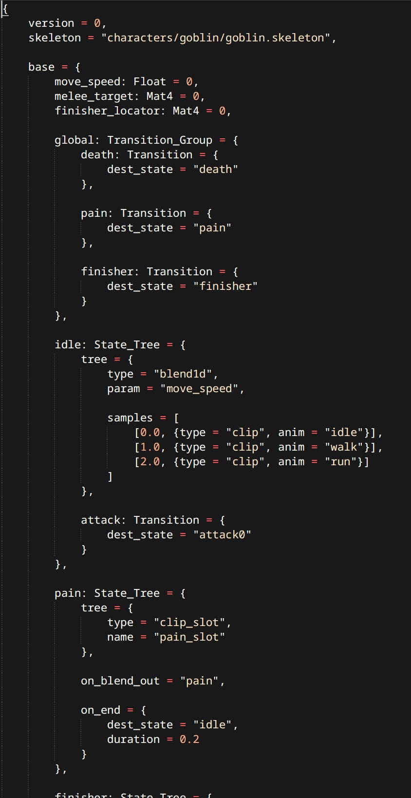
Text is very easy to work with. Simple to parse. Makes it trivial to add new nodes, but more complex graphs get confusing to work with. I should probably invest in a graphical editor at some point.
Execution
Correct order of execution is crucial for correct results with all the animations, procedural adjustments and physics.
Gameplay logic sets graph variables & requests state transitions.
Anim Graph evaluates - producing root motion and Pose Tasks.
Character Controllers are moved using the Root Motion.
Pose Tasks get evaluated producing final animated pose. Separation of Root Motion and pose evaluation is important so that Foot IK Nodes can query physics world when the character is at its correct position.
Final graph pose is fed to the Ragdoll which will either match it perfectly, attempt to do so using constraint motors or just be limp.
Physics simulation is run.
Pose from the Ragdoll is transferred back to the one used for skinning.
Pose Tasks
(In code named Anim Tasks) Anim Graph does not generate poses during it’s evaluation. Instead it registers Pose Tasks. Which are similar to a command buffer. Tasks are low-level constructs any Anim Node can record multiple of them. Some Anim Nodes serve as simple wrappers for tasks. Examples of tasks include:
Sample Anim Task - Samples an animation given the clip and time.
Blend Anim Task - Blends two poses given 2 input tasks and a weight or mask.
Two Bone IK Anim Task - Performs the actual IK logic. The Two Bone IK Node is a thin wrapper generating this task.
Write / Read Cached Pose Anim Task - Poses can be saved and restored. Useful for when transition has to blend from another transition, in which case the oldest state is not updated or present. It’s pose is simply saved. Transition can read it and use it for the blend.
Pose tasks can be used for things like animation Level of Detail. e.g. characters further away can skip IK tasks, or even blend tasks.
Audio
Currently the audio system is a simple wrapper on top of OpenAL. It has a pool of Sound Sources that get assigned to sound requests. I have done very little work on audio but I’m looking forward to doing more.
Physics
If you were to ask me ‘which is more important Animation or Physics?’. I would say - ’yes’. They’re both part of the same whole. Physics is the Yin to Animation’s Yang. Interaction between the two is the biggest factor affecting the ‘Game Feel’.
The Physics Engine
While I like to write my own solutions, physics is not something I feel equipped to tackle (just yet). Using an existing physics engine was an obvious choice. Which one? Answering that wasn’t obvious at all.
I started off by integrating Nvidia PhysX 4. It’s fast, open source and most importantly of all - battle tested. Shipped in approximately half the games to ever even have physics. A strong contender.
Before I got too deep. I thought about using Bullet Physics - my first physics engine. It is very easy to use and a lot of people begin their physics adventure with bullet. Unfortunately the performance leaves a lot to be desired. Even when compiled in multithreaded mode it doesn’t even come close to PhysX.
Then this newcomer shows up. Out of nowhere Jolt Physics goes public. An Open Source Game-Oriented Physics Engine already used in a major AAA title - Horizon: Forbidden West. With a strong focus on multicore simulation and concurrent access.
Unlucky for me with Jolt being so new there were no available comparisons of how it stacks up with the others. So I did the unthinkable… I integrated all 3 Physics Engines at the same time!
Being able to switch between them easily I compared them myself. Spawned a bunch of bodies, threw a bunch of ragdolls…
Very quickly turned out bullet’s performance is abysmal. Bodies like to penetrate the world triangle mesh. CCD is all but necessary. Collisions with triangles are always two-sided making ragdolls get stuck in walls easily. It is clear bullet was never written with multicore processors in mind. It is a mature popular physics engine which started development in the 90s, and that shows both in the good and the bad.
PhysX was my clear favorite. Incredibly fast, robust and can run on multiple cores no problem. Some of the main downsides I observed were:
Debug Visualization was very slow. Referring not to the cost of rendering it, but just having it generated inside of PhysX.
Joint Drivers were unintuitive and hard to match a pose with. In retrospect I should have probably used Articulations instead of regular joints.
Multithreaded access boiled down to: locking the entire physics scene → performing the changes → unlocking the scene. Having such a broad locking scheme would require careful consideration when to use it and how. At the time I have done nearly no multicore programming so that was an obstacle.
I was very interested in Jolt not just because it was new. Mostly because it already shipped in a massive game. I checked out the samples included in the repo. Needless to say I was impressed. Ragdolls matching animations, piles of bodies, everything I wanted to see. Jolt has a strong focus on multicore simulation and concurrent access to the simulation. ‘You already said that but what does that mean?’
Jolt has a lockless broad phase. Entire quad-tree is driven by atomic operations only. Making it very fast. Another thing is the ‘BodyInterface’. Body Interface is a middleman between the user and the actual bodies. It handles locking at granularity defined by the user. So gameplay code doesn’t have to concern itself with locking at all!
Sounds like a sales pitch - I know. But all of that has downsides as well. Lockless broad phase means quad-tree nodes can only ever grow. Which will result in degradation of performance over time. There are a number of things the user has to do to accommodate this limitation:
Multiple broad phases. In Jolt’s examples basic distinction is made between dynamic and non-moving objects. Each kind of object lives in it’s own broad phase. Collisions between them can be filtered just like normal collision layers present in all physics engines. Meaning the static borad phase nodes never grow. Static geometry is usually the majority of bodies present in a game simulation.
Call OptimizeBoradphase(). This is a blocking call that’s gonna tighten up the node bounds in place.
Batch add bodies. Adding bodies one at a time can degrade the broad phase very quickly. Jolt’s mechanism for adding multiple bodies consists of building a subtree which is then slotted into the proper broad-phase all at once (atomically of course). Resulting in tighter nodes overall.
Updating the system even when paused. Jolt’s documentation explicitly recommends updating with 0 delta time even when the simulation is ‘paused’. It also helps with quad-tree behavior.
That being said. I decided to go with Jolt. I’m not gonna lie it being the new thing played a factor, but it was not an emotional decision.
Basic Physics Primitives
Of course my engine supports the use of all basic physics primitives: rigid bodies, constraints, shapes, queries and various kinds of filtering. All of those are more of a physics engine topic rather than a ‘game’ engine topic. Hence I will not elaborate on these, since they’re mostly thin wrappers around Jolt.
Ragdolls
What’s more important for game enjoyment? Graphics or Ragdolls? Obviously the answer is Ragdolls! It’s just a bunch of bodies connected by constraints, what’s there to talk about. Well quite a bit.
Authoring
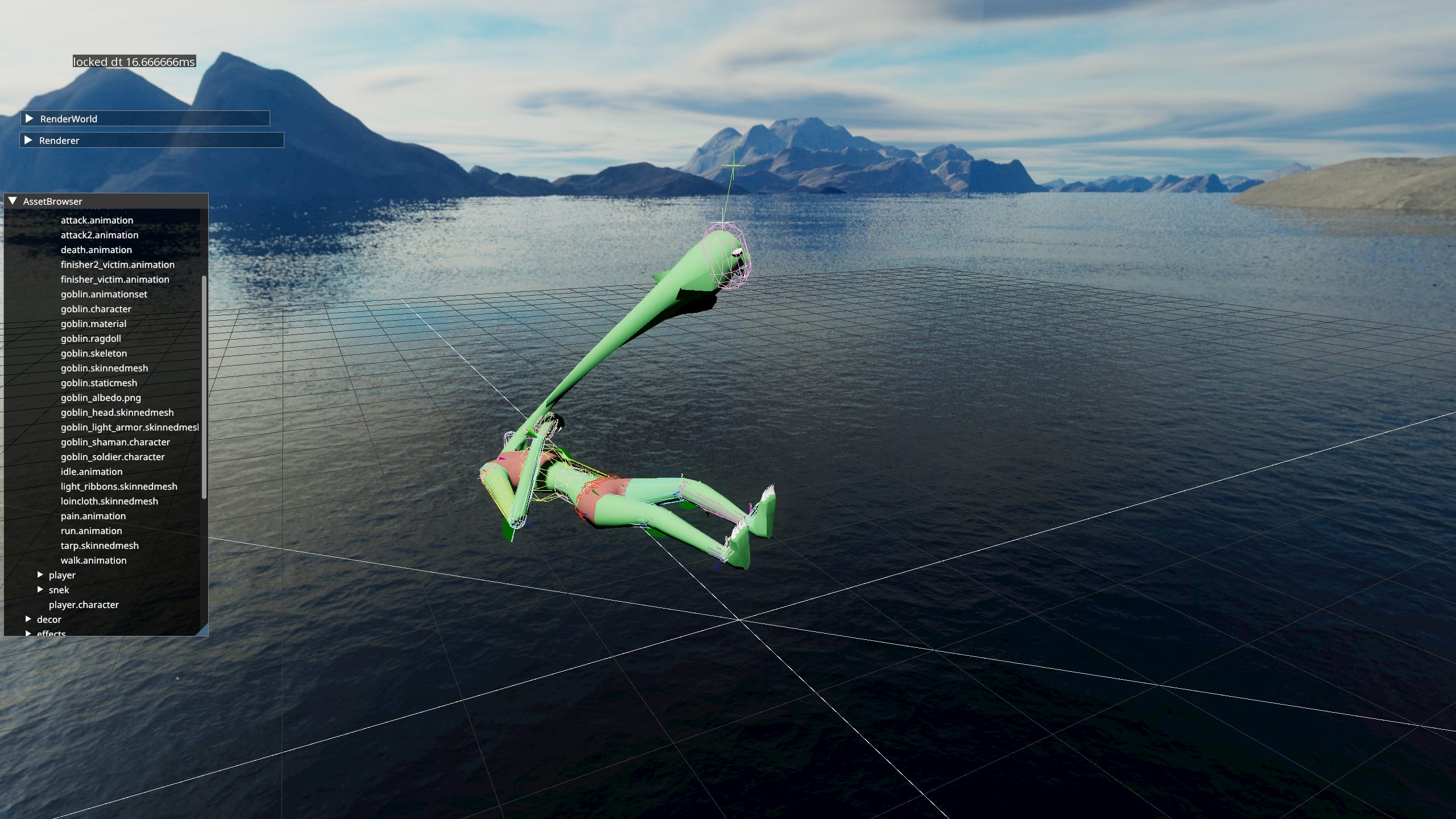
The first problem I encountered when attempting to implement ragdolls was not the conceptual understanding… that is actually quite simple. It was creating them. So the very first tool the game ever had - Ragdoll Editor - was created.
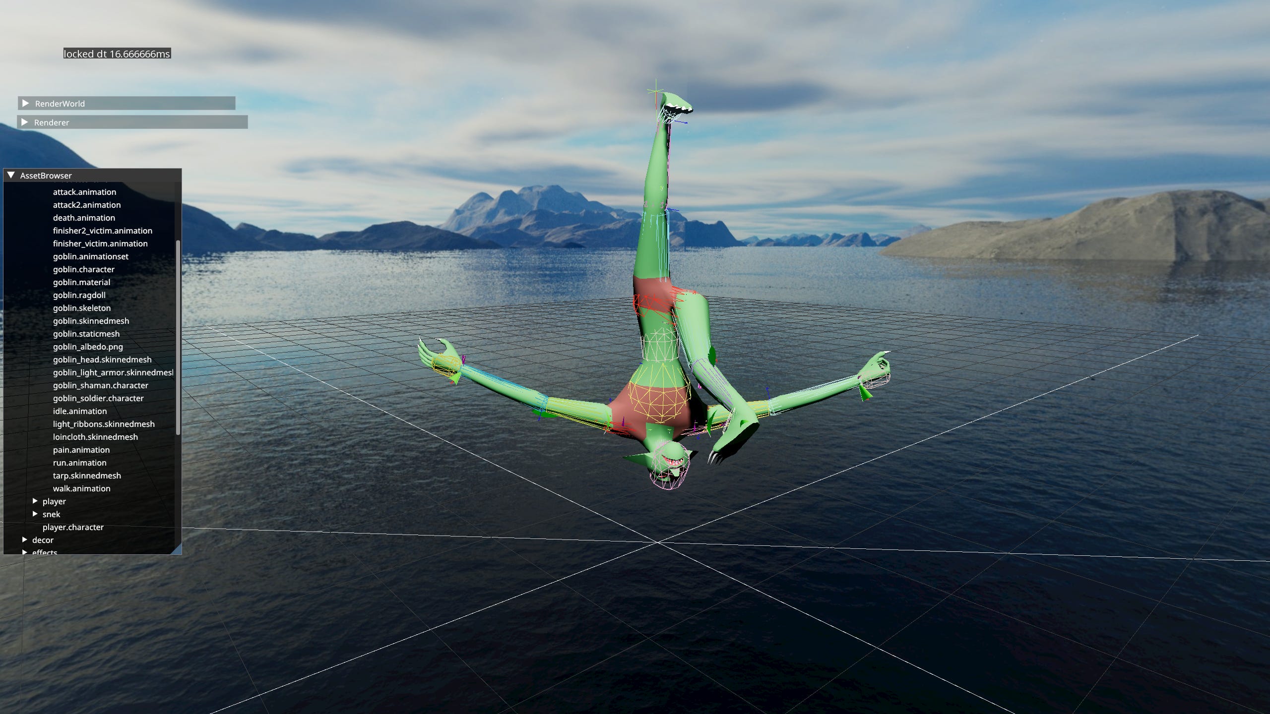
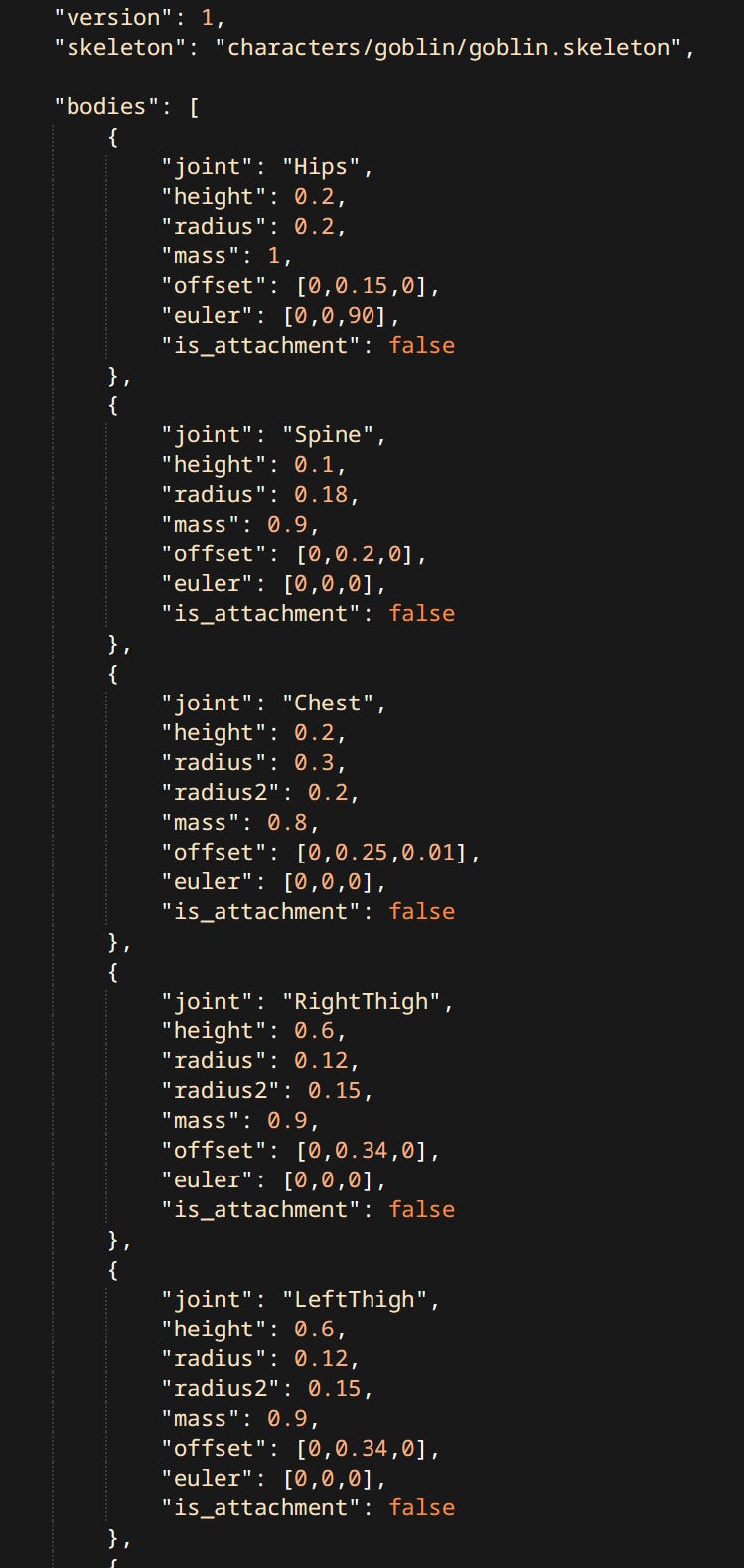
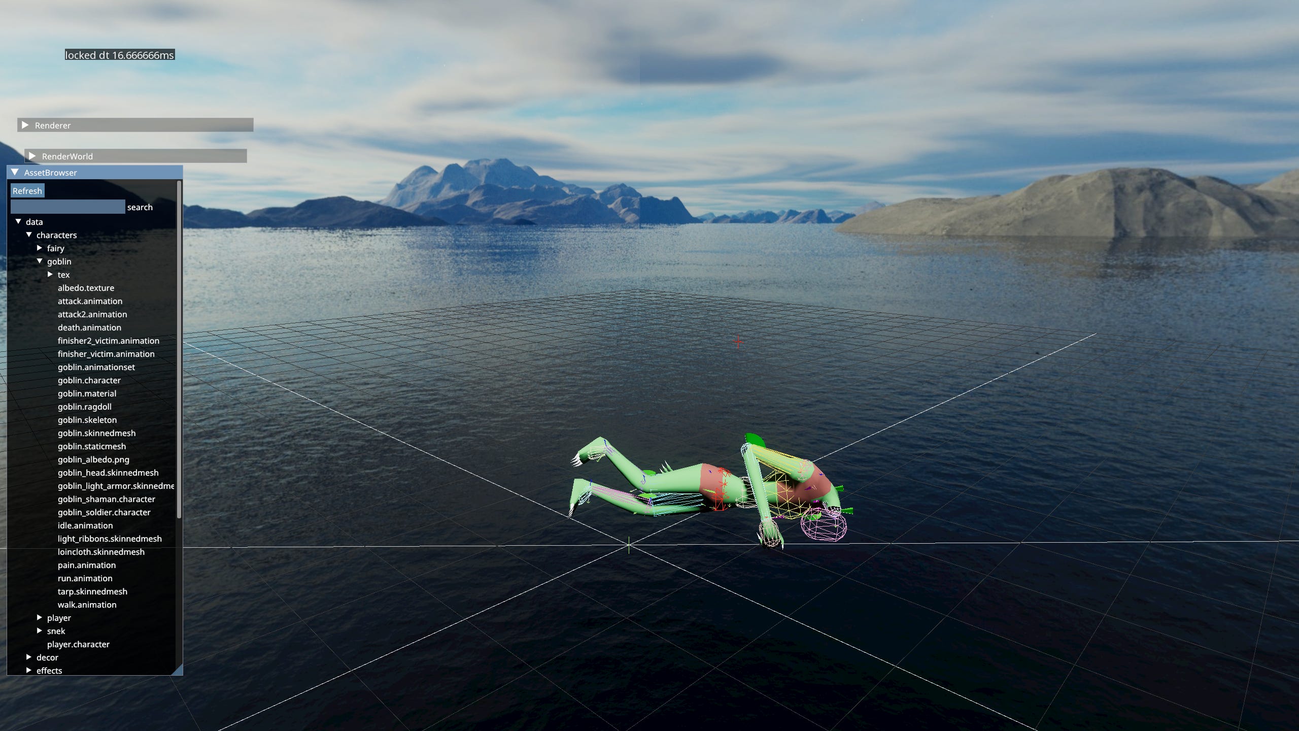
Though calling it editor may have been a bit of a lie. It doesn’t actually allow you to edit the ragdoll - only preview it. The actual data is edited in a text file. An ADF like all other assets. Ragdoll Editor can only reload it at runtime. Has basic facilities like starting / stopping the simulation, dragging bodies and switching Ragdoll Profiles. Ragdoll’s ADF is a long list of body properties, constraints, filters, profiles and body parts.
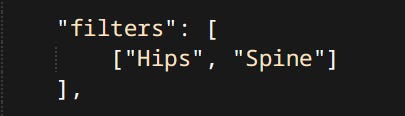
Filters
By default bodies belonging respectively to a parent and a child are filtered out automatically form colliding with each other. Sometimes other pairs of bodies need to be filtered as well.
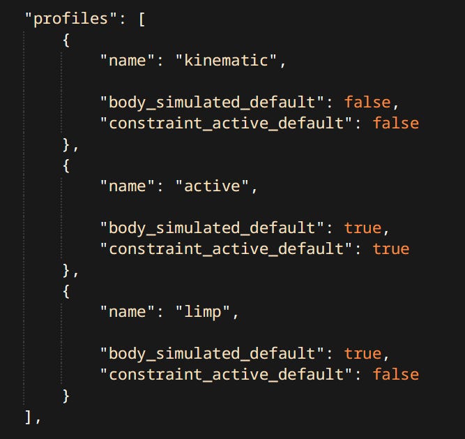
Profiles
Profiles are sets of states for each body and constraint. States are: is the body kinematic or simulated. Is the constraint active or not. Each ragdoll is expected to have three basic profiles: kinematic, active and limp.
Kinematic profile is used when the character is fully alive and being controlled by gameplay code.
Active usually means the bodies are simulated but constraints still try to match the animated pose. Used while characters are dying or being thrown around.
Limp meaning the ragdolls position is driven exclusively by simulation results.
Details of the profiles can differ. For example Snake’s tail is always physically simulated no matter what. Any configuration that satisfies these definitions is valid. Due to the nature of how profiles work it’s possible to have any number of them but that’s not really used.
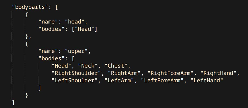
Bodyparts
There’s one more thing that ragdolls can do, and that is… be dismembered! The way this works is not as simple as disabling a constraint unfortunately. Since ragdolls are driving skinned meshes the transforms of ‘chopped off’ limbs still need to be accounted for.
Bodyparts are collections of bodies from the ragdoll. Defined in the ADF:
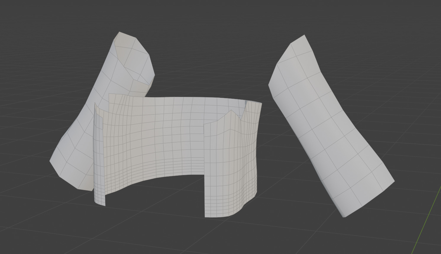
The way dismemberment works in my game is:
The gameplay code requests a certain part of a character to be dismembered.
The relevant meshes are hidden and Dismember() is called on the ragdoll instance. Dismember takes the name of a body part defined in the asset file. That makes the limb disappear.
Now for the giblet itself another entity is spawned. It contains a skinned mesh of the cut limb, and another Ragdoll instance. On that ragdoll an operation called InverseDismember() is performed. It does the exact opposite of Dismember() and disappears all the bodies that are NOT part of the provided body part. Giblet entity then copies the pose from original character and carries on.
Example of dismemberment in practice:
Cloth
I have a bit of an obsession interest with cloth simulation. One of the elements that elevates the game feel. No matter the game, the genre, the console generation - adding cloth always makes it better!
Game cloth simulation existed in some form pretty much for as long as 3D games did. From PS1 Lara Croft’s Braid to Ghost of Tsushima’s everything. As it turns out the method of simulation hasn’t changed very much over all that time.
Simulation Overview
Nearly all game cloth simulations use basic Verlet cloth, or at the very least some other position-based method. Like PBD.
Position Based Simulation - In traditional sequential impulse solvers, used in most physics engines. We compute impulses which modify velocities which in turn get applied to positions. Position based means we compute the final position and then use the delta to derive our new velocity. This method is perfect for cloth since there’s countless constraints acting against each other, making exploding virtually impossible.
Simulation steps are:
Integrate motion using Verlet integration per particle.
Constrain particles to their skinned positions based on provided distance.
Collide against shapes representing the character.
Enforce distance constraints amongst the particles.
Enforce long range attachments.
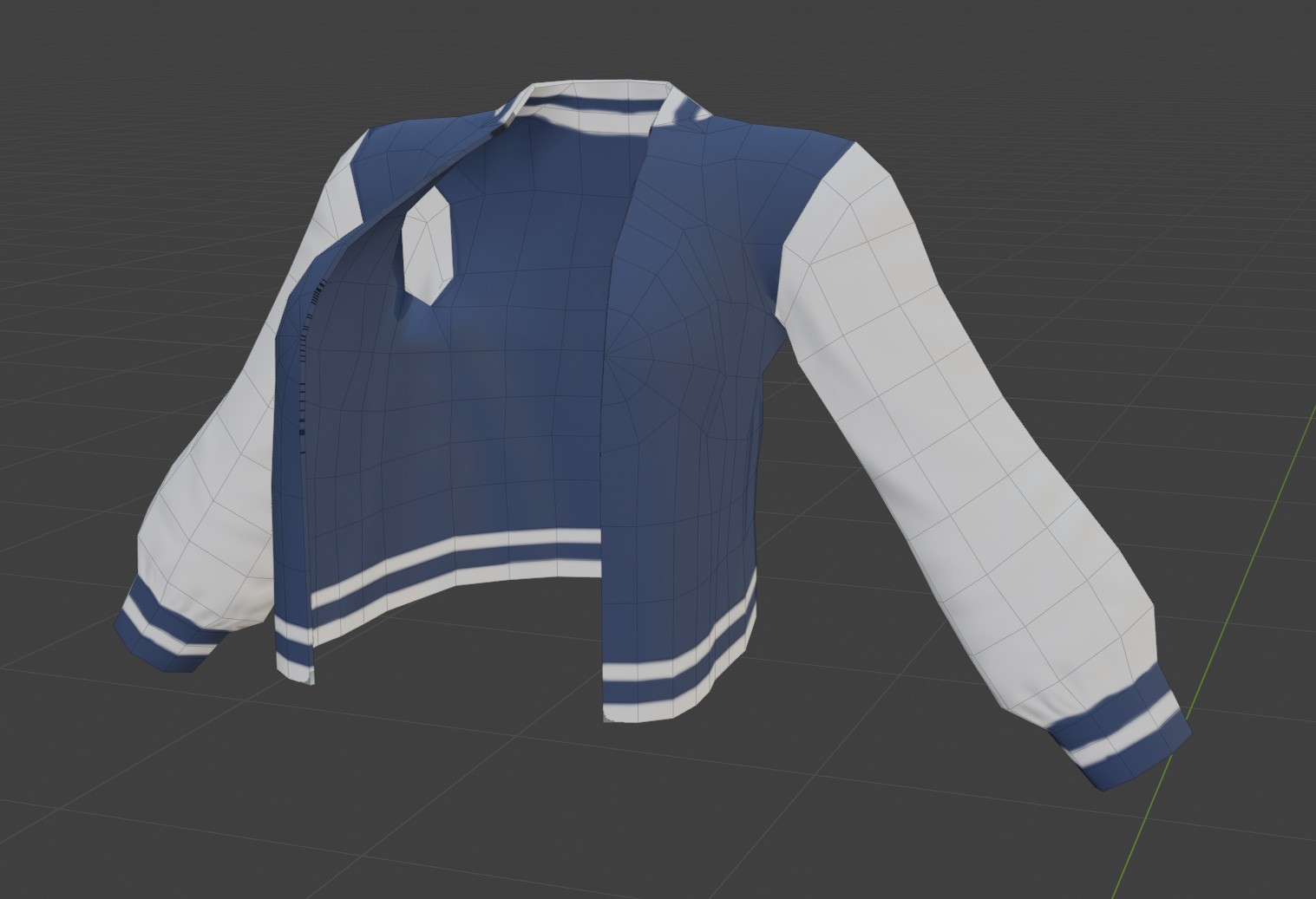
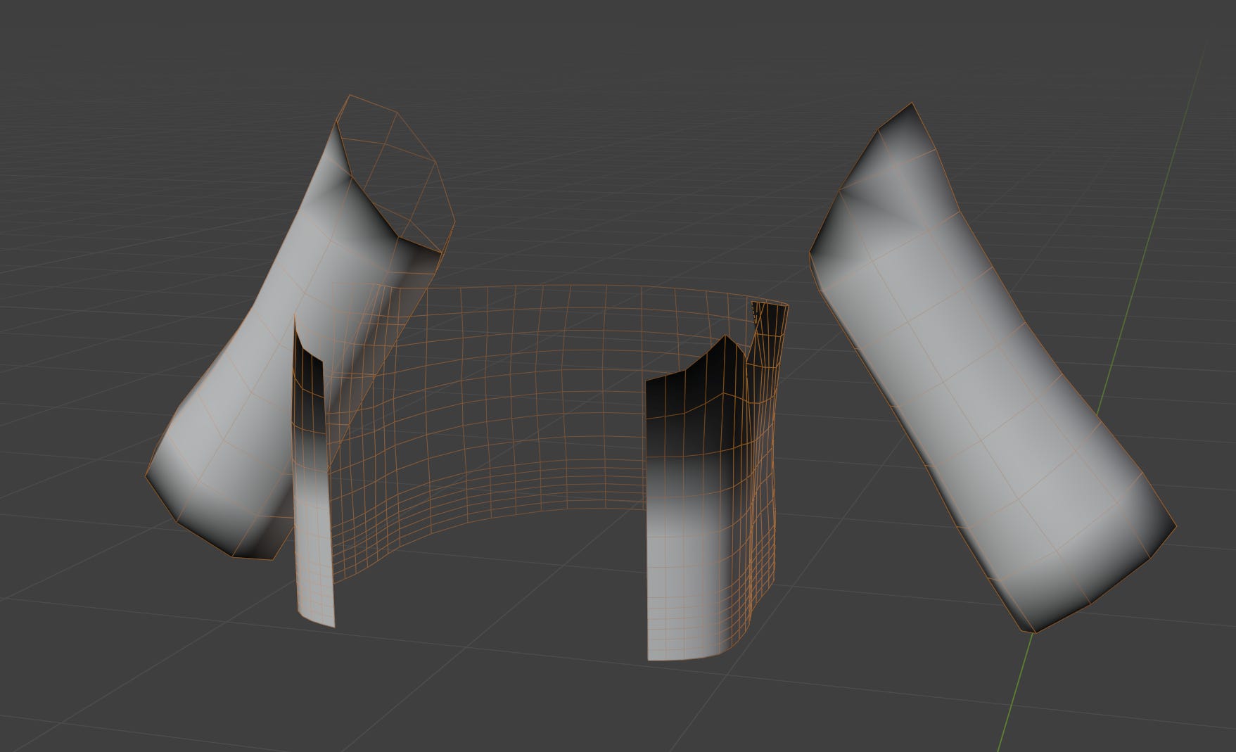
Skinning
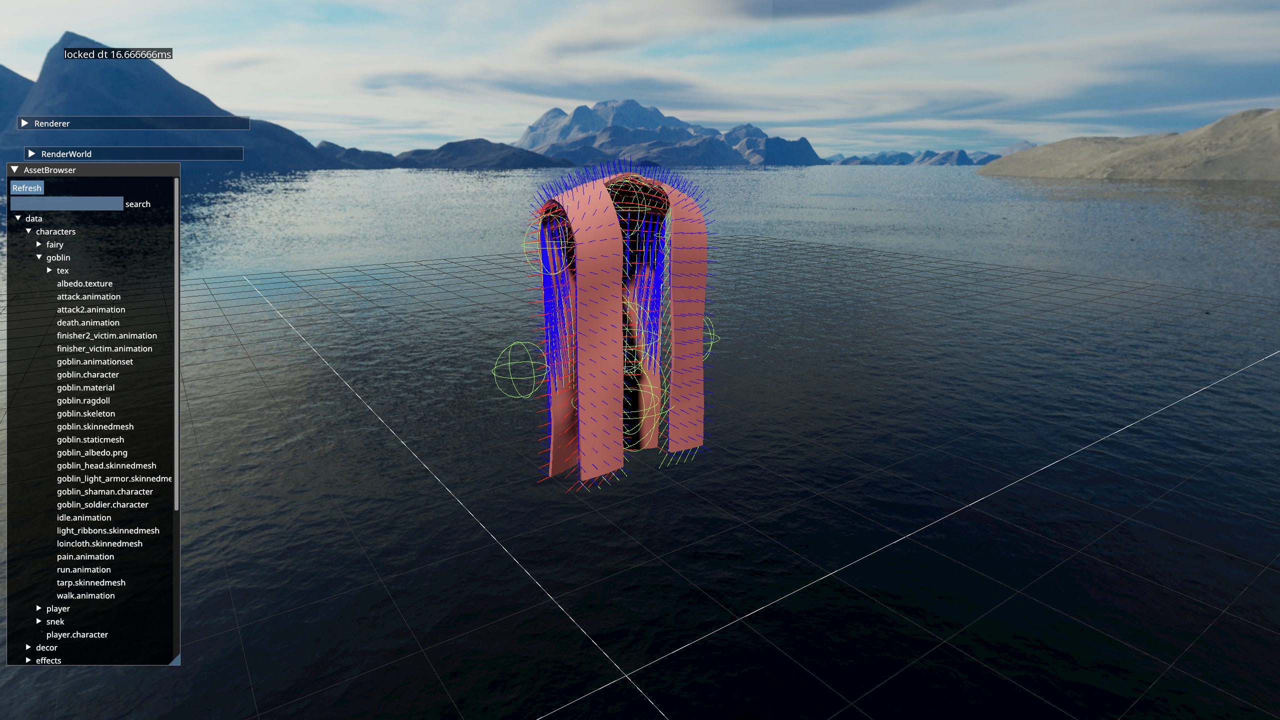
Cloth instances are actually two meshes. The low resolution simulation mesh that drives the simulation, and high resolution render mesh the one player sees.
Simulation mesh is skinned to the animation skeleton, that mesh’s vertex positions, normals and tangents define joints of their own. High res mesh is skinned to those joints.
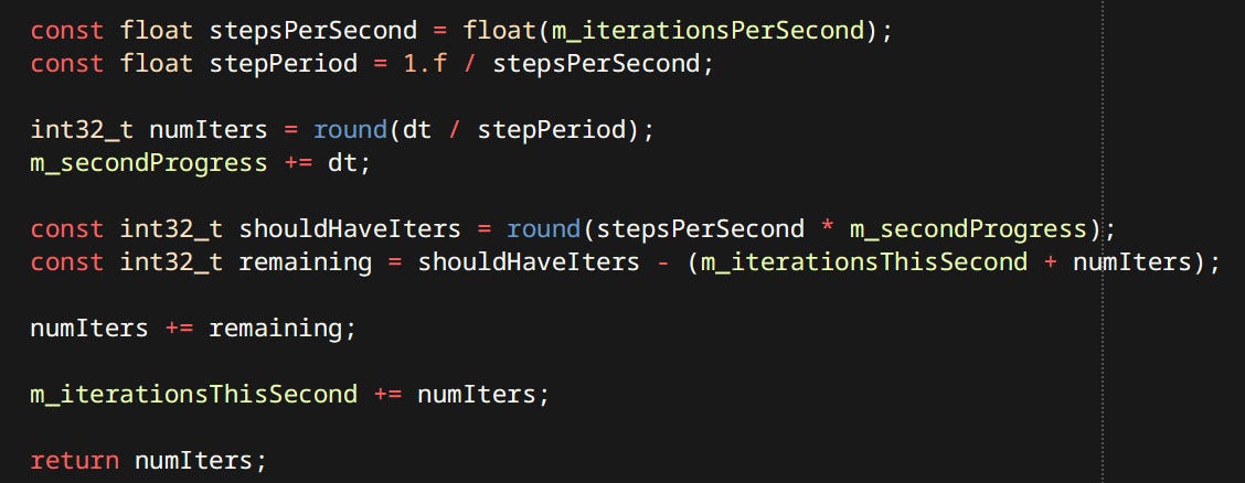
Simulation Frequency
My cloth simulation like any other physics simulation is dependent on the timestep. I have a simple mechanism to perform a fixed number of iterations per second. Default is 240Hz which divides nicely to 4 iterations per frame at 60fps.
Collisions
Each cloth article has a number of Collision Spheres which can be connected to form Tapered Capsules. Good for approximating characters and cheap to compute. The spheres are attached to animated joints of the character. Due to the fact that number of iterations is usually much higher that the number of frames per second, the system cannot receive up-to-date data every iteration. To combat this every piece of data externally provided is interpolated. Interpolating the simulated vertices would make sense if the number of iterations was much smaller then frames per second i.e. during slow-motion. That functionality is currently not supported.
Constraints
Constraints (or Links) between simulation vertices follow the edges of mesh’s triangles. They form the surface of the cloth article. They also go across the triangles to prevent excessive bending.
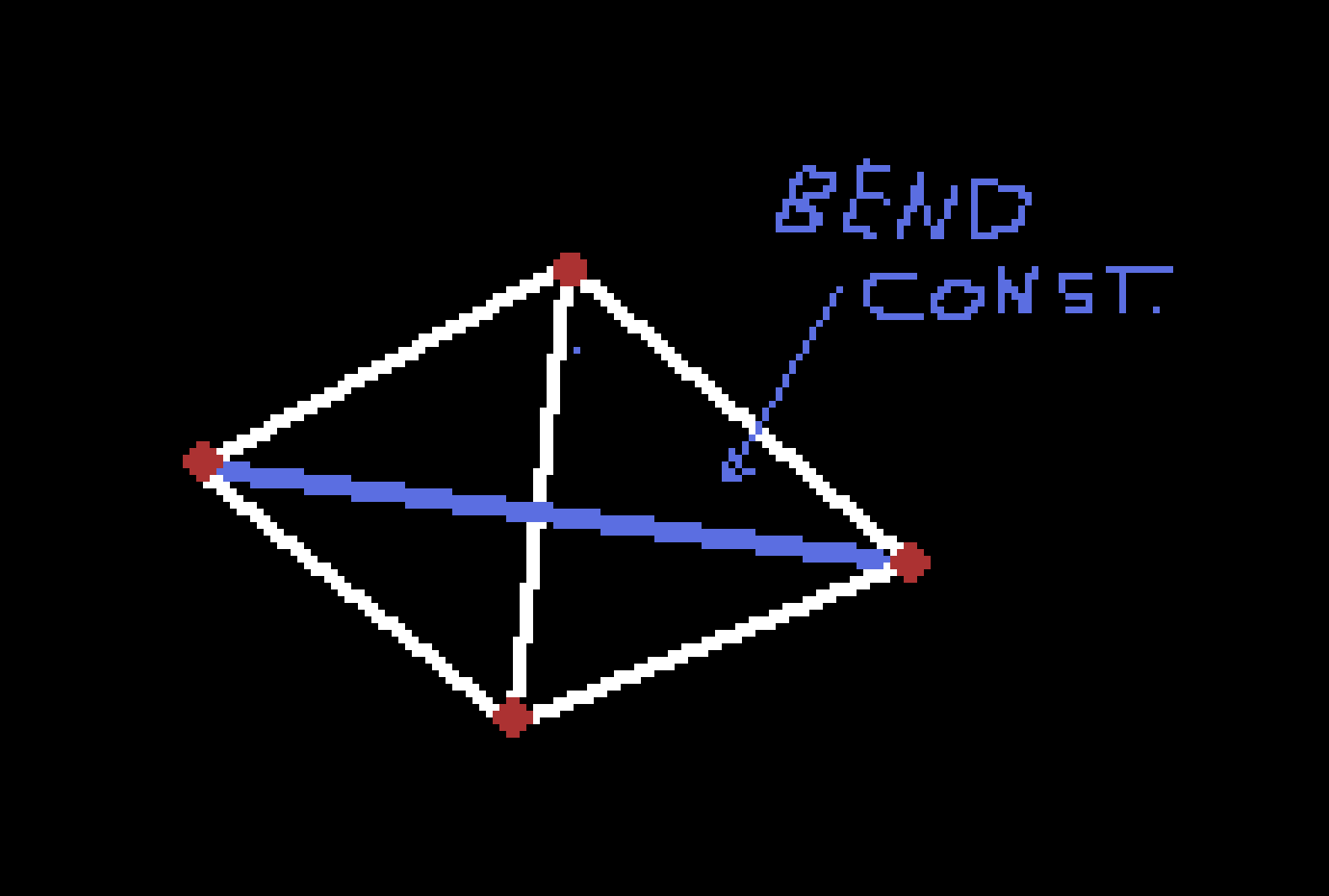
Due to low number of iterations (one) those constraints alone cannot prevent stretching.
Long Range Attachments
To prevent stretching Long Range Attachments (LRA) are used. (also known as Tethers or Anchors). Each simulated vertex is connected to the closest kinematic vertex based on geodesic distance. Mesh is walked along the constraints using Dijsktra’s Algorithm and index is recorded for each vertex. To my knowledge LRA are only used in game cloth.
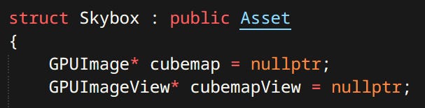
Asset
Cloth data is stored inside the Skinned Mesh Asset. Currently cloth cannot exist on it’s own. It has to be displayed using a skinned mesh. So far this limitation has not been a problem.
GPU Cloth
Next step in improving the system would be running the cloth on the GPU. Then both simulation and skinning could run faster. Since cloth sim is purely cosmetic, there’s no reason to exchange data with the CPU during the simulation.
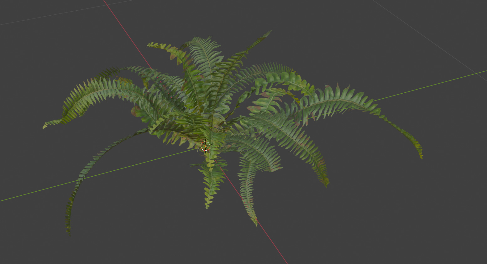
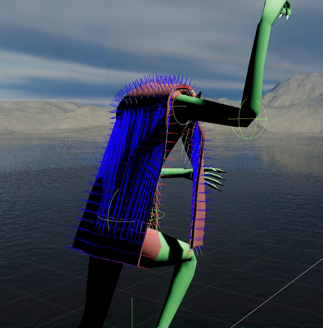
Foliage
Foliage simulation is very similar to cloth. There are two differences.
Vertices are spawned at joint positions. Joints then match positions of sim vertices.
Each vertex gets pulled in a forward direction of the corresponding joint. This allows the plants to stay upright and return to the default position after being disturbed.
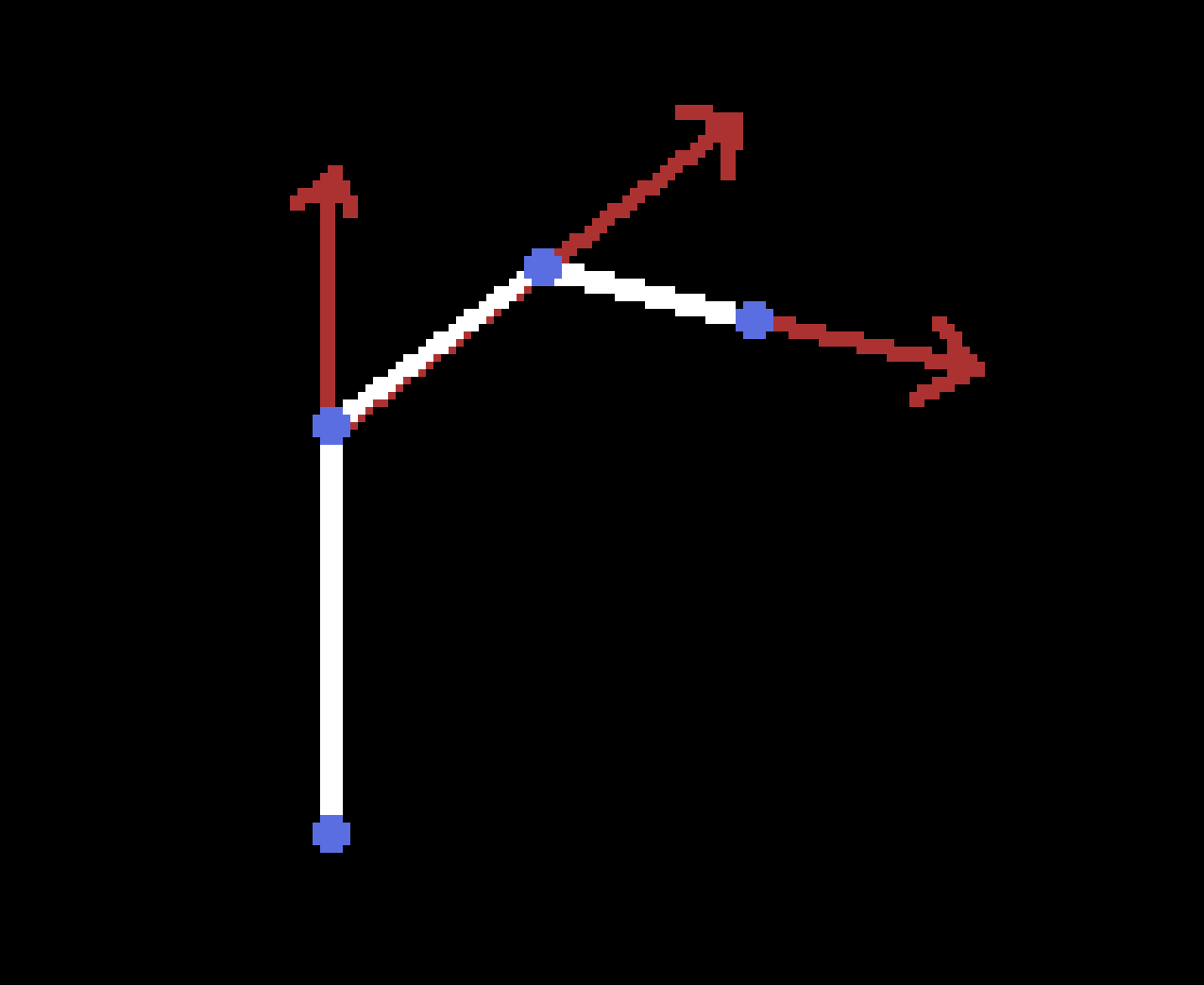
Vertices being pulled in joint’s forward direction

Foliage sim in action:
Currently foliage simulation is pretty raw. There are no optimizations. I plan on adding a basic broadphase step and actually parallelizing the system.
Rendering
An important yet dare I say overly focused on subject. Which does not mean I didn’t overly focus on it - I did. I had a few goals for my renderer:
Physically Based Rendering
Level of Detail support
HDR Lighting
Precomputed Global Illumination
GPU Driven Rendering
RHI
I once heard someone say ‘Using Vulkan is like writing your own graphics driver’, and I thought to myself ‘Ok stop selling it - I’m in!’. Turns out that after the initial shock of moving from the highest levels of OpenGL to the magma filled depths of Vulkan, I like it much more. I’m a bit of a control freak and Vulkan gives me all of it and then some.
Shader Compilation & Management
Since I come form OpenGL background I also use GLSL in Vulkan. The shader pipeline is very simple and separate from other assets (Though maybe shader should just be a type of asset). Shaders are compiled offline with a simple shell script. For that purpose I employed glslc.exe that comes with Vulkan’s LunarG SDK.
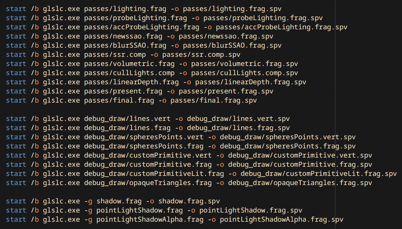
The shaders that engine loads are just binary blobs of SPIR-V.

I could probably go the extra step and embed a shader compiler but this is really not a limitation since shaders can be reloaded at runtime.
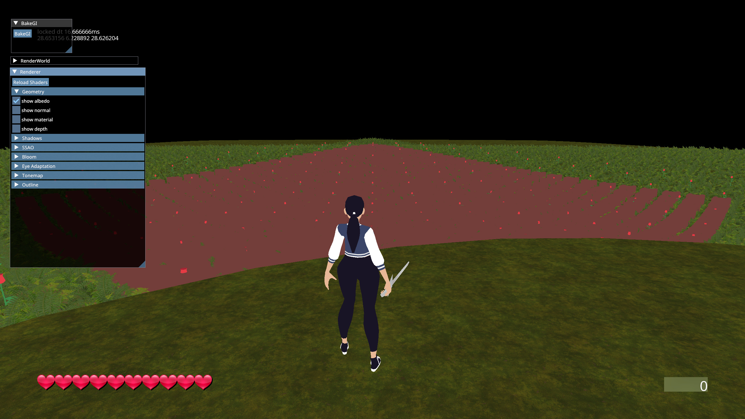
General Architecture
This renderer uses what is called Tiled-Deferred rendering. Deferred relating to use of a full G-Buffer. Tiled referring to light binning as described in Forward+. The overall structure is quite simple. Main components are:
Render World - Render representation of the level. Contains scene dependent data like meshes, lights, particles, decals, probes, etc. Inspired by it’s namesake RenderWorld from idTech 4. If ‘render entities’ need special consideration, say point lights need to be packed tightly into a GPU buffer - this is where it happens.
Renderer Resources - Contains mostly render targets and some other resolution / setting dependent data like shadow maps and light tiles.
Renderer - A set of Passes and Sub-Renderers. Takes the Render World, Renderer Resources and settings as input, then executes passes in sequential order. Passes use Sub-Renderers inside.
Sub-Renderer - Handles rendering of a specific type of thing, like particles or a skybox.
Renderer Pass - Performs the actual draw calls, uses outputs of previous passes in rendering.
Render Entities
Render entity is not a formal concept in my engine. It’s an umbrella term for visual stuff in the world. There’s a few different kinds:
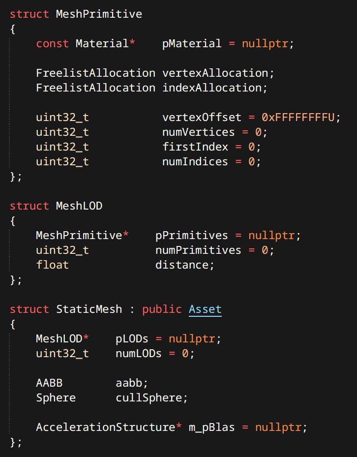
Static & Skinned Meshes - Most numerous by far. Used for characters, environments, items, etc.
Mesh is a collection of LODs. Each LOD is a collection of primitives. Each primitive represents a piece of geometry equivalent to one material slot. Mesh primitives are the parts that actually get drawn.
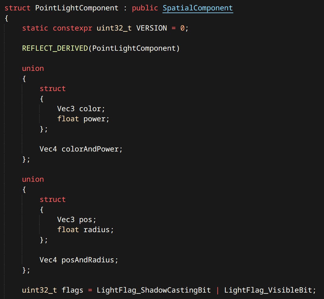
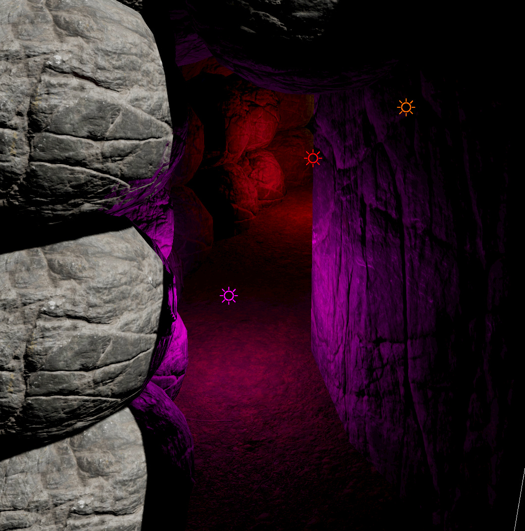
Point Lights - Omnidirectional light with inverse square fall-off. Has a limited radius. Can optionally cast shadows. Currently the only type of light supported (other than the sun).
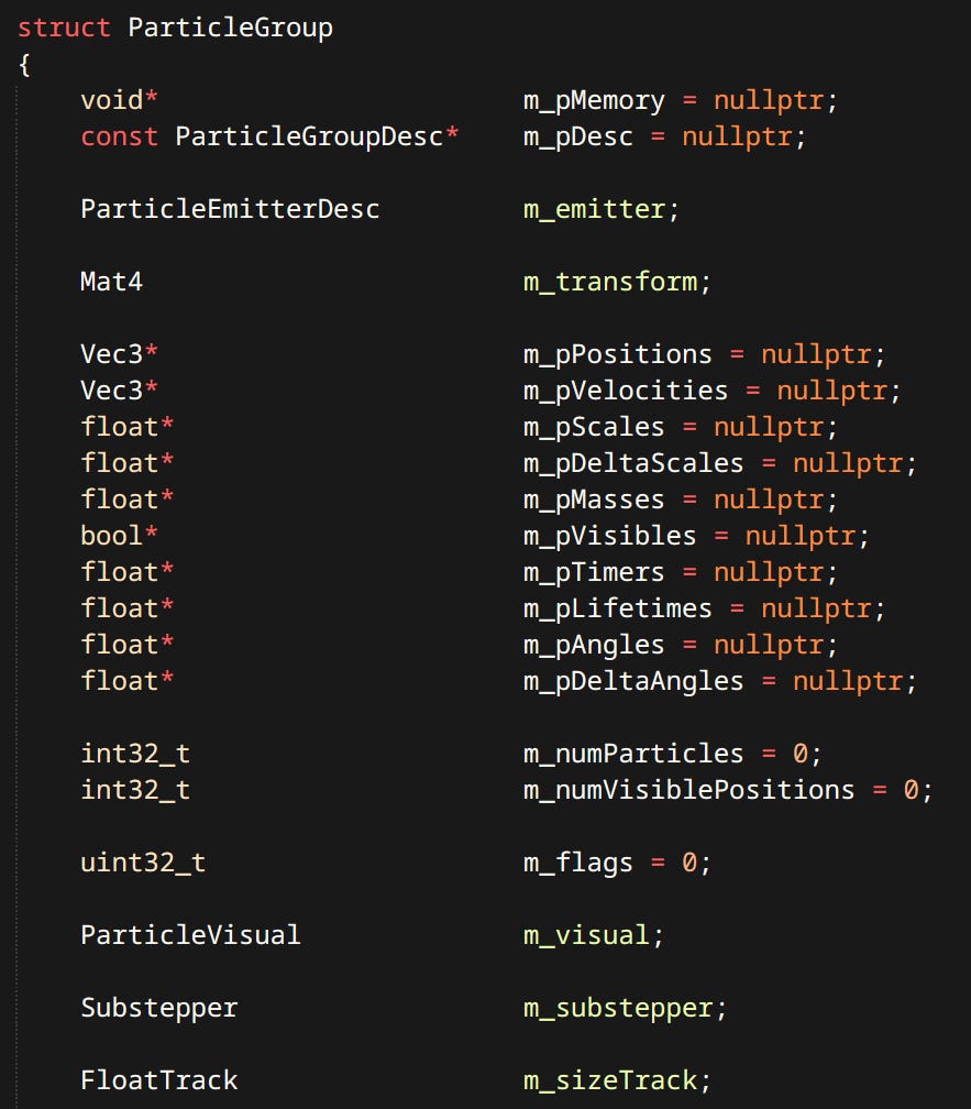
Particles - Particles are simulated on the CPU. Can be rendered as billboards or meshes.
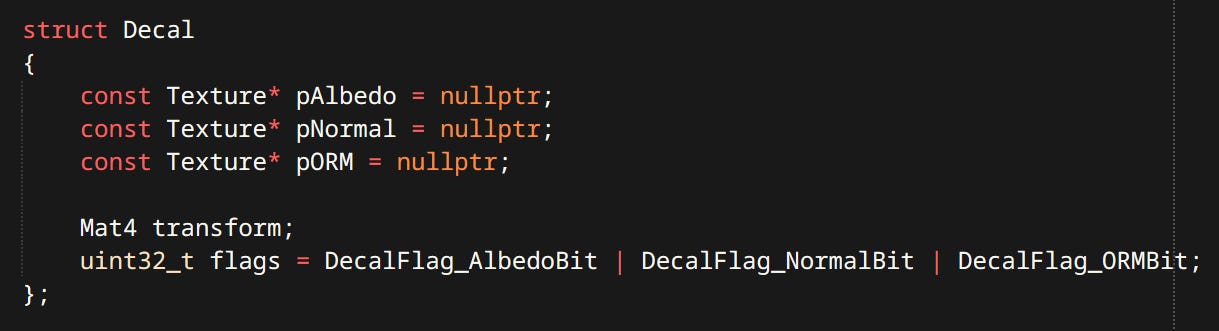
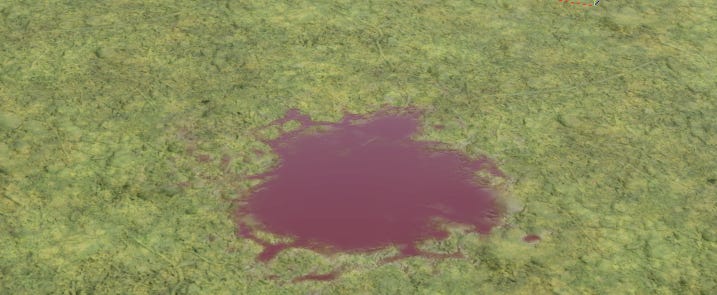
Decals - Modify the surface properties of whatever is contained in the projection box. Currently exist in deferred form not making use of tiles, though they should.
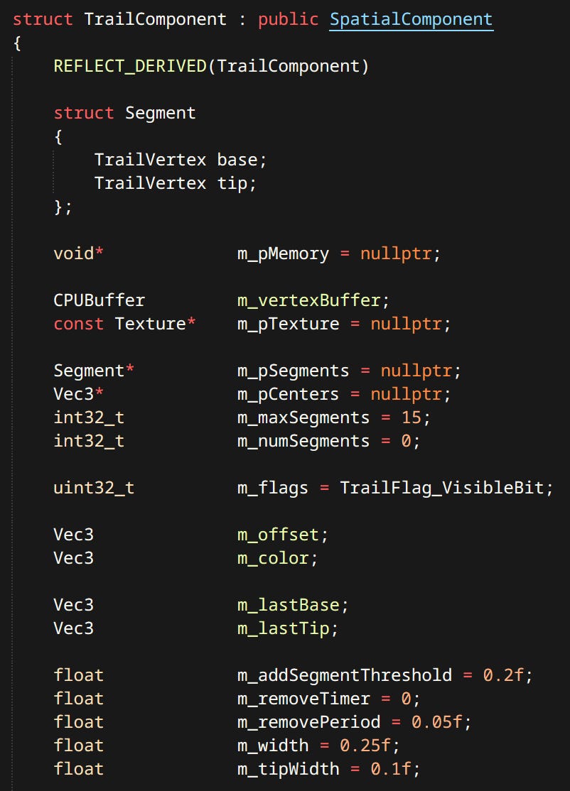
Trails - Trails are a ribbons left by either an oriented line or a singular point.
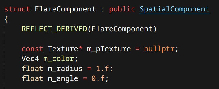
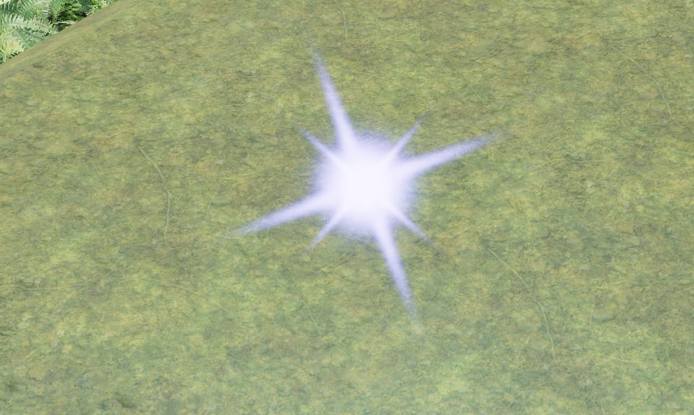
Flares - Flare is a billboard sprite oriented towards the camera. Can be alpha blended or additive.
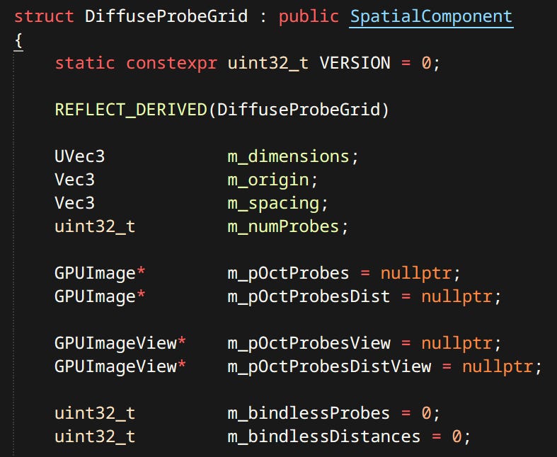
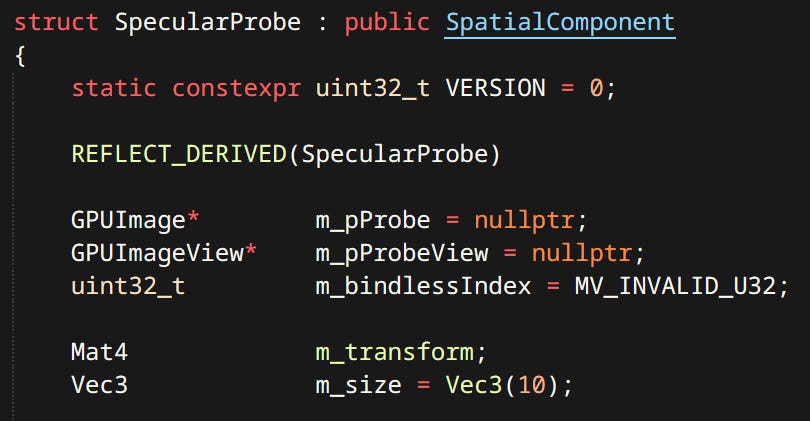
Probes - There are girds of diffuse probes and individual specular probes. Probes are sorted by volume and blended when sampling.
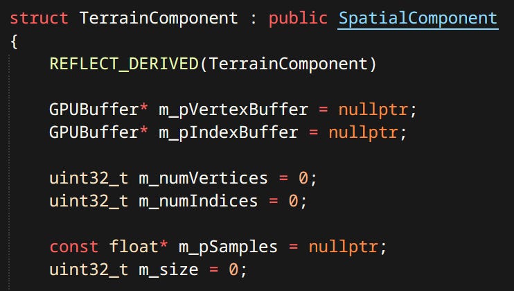
Terrain - Terrain is defined by a 2D grid of height values. Currently terrain implementation is very fresh and supports only one texture. Since terrain tiles are unique there’s no need to instance anything.
Skybox - A simple cubemap background.
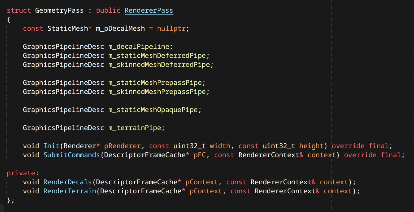
Passes
Passes are almost pure transformations. Contain only PSOs needed to perform their respective functions. They select data from RenderWorld and render it into targets contained in RendererResources.
These are the most important passes. There are more unused and miscellaneous ones not covered here.
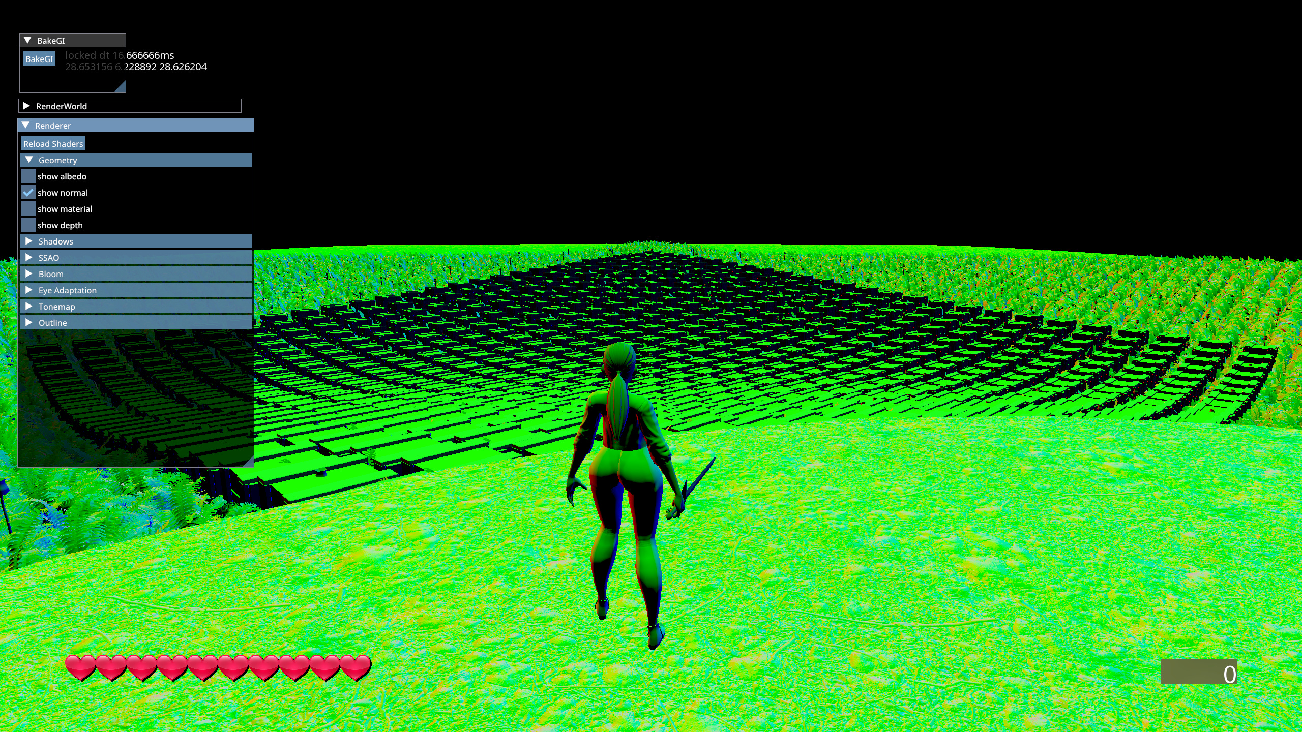
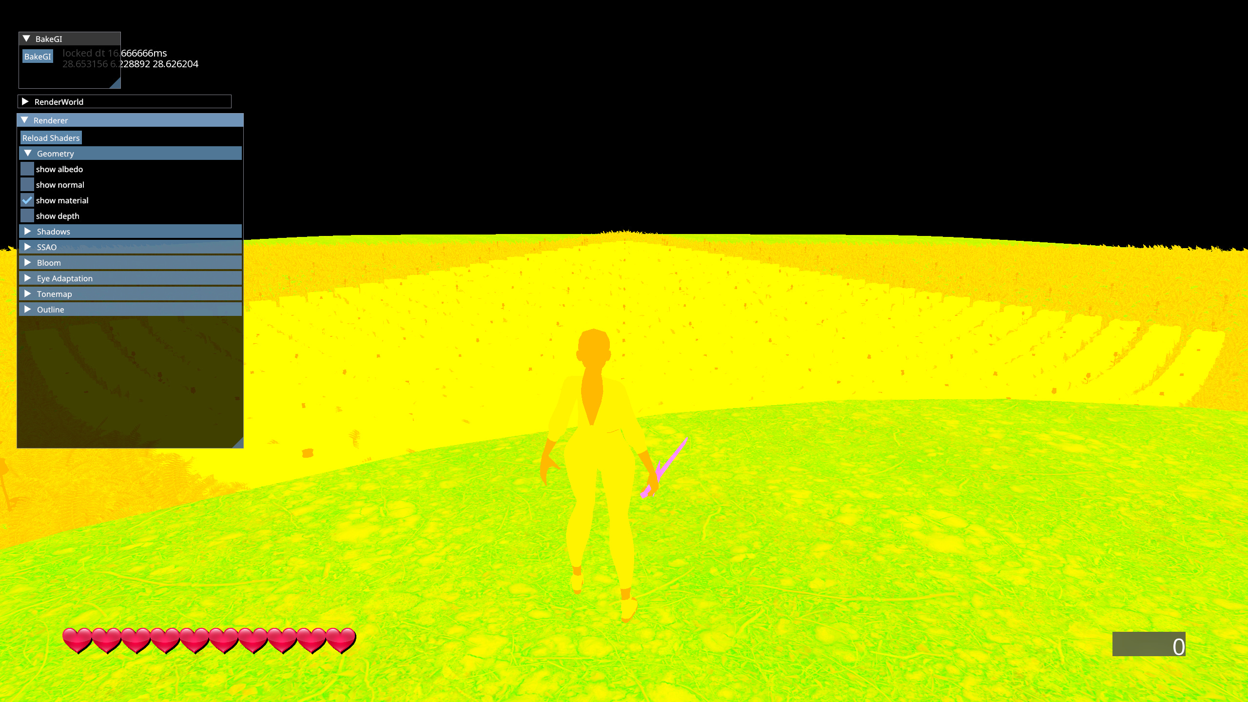
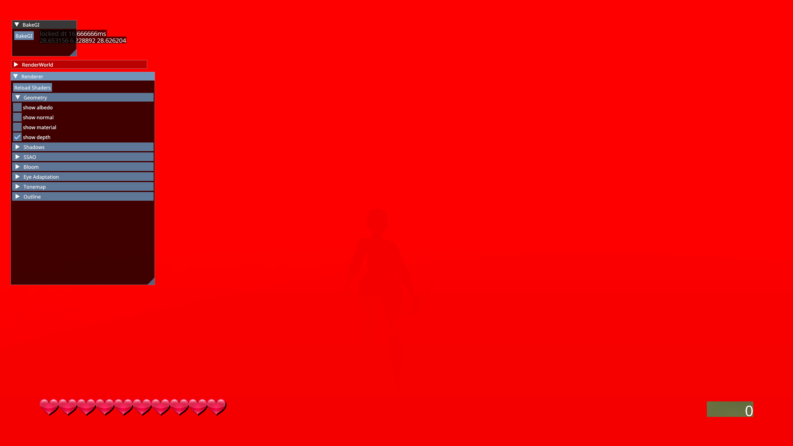
Geometry Pass - Populates the G-Buffer with any geometry that’s subject to main lighting calculations. G-Buffer is used for more than just lighting. Meshes are culled on the GPU before drawing. This is the part that makes the renderer deferred.
Shadow Pass - Responsible for both sun shadows and point light shadows.
Shadow cascades are orthographic projections boxes wrapped tightly around slices of the view frustum. Each cascade is the same resolution but covers different area, so closer cascades appear higher resolution.
Point Light shadows are cubemaps of linear distance. There are 4 shadow cubemaps that get assigned to the closest 4 point lights with shadow casting flag. Two closest maps are higher resolution.
SSAO Pass - The SSAO method I used is ‘Normal-Oriented Hemisphere SSAO’. Similar to classic Crysis method but doesn’t have the convex edge highlighting artifacts.
A hemisphere of sample points known a the ‘kernel’ is placed on the surface sampled from the G-Buffer and oriented around a normal also sampled form the G-Buffer. The kernel is then rotated based on a small 4x4 noise texture. First step is performed at half resolution.
Due to the noise texture the blur only has to extend 2 pixels in any direction. Output of the blur step is full resolution.
Light Cull Pass - Lights are culled an binned just like described in the original Forward+ paper. This is what makes the renderer tiled.
The view frustum is split into slices corresponding to 16x16 pixel tiles.
Each ‘sub-frustum’ is 4 planes. These are packed into a GPU buffer.
Lights themselves are also packed into a GPU buffer.
A compute shader then culls each light against each tile and fills both a texture called ‘light grid’ and a buffer with lists of light per tile.
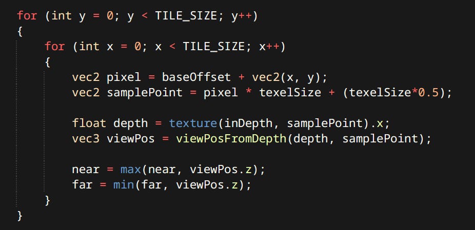
First the shader determines minimum and maximum depth of geometry present in it 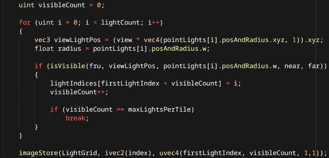
…Then tests the point lights against the frustum planes to determine influence and stores results in the light grid Light grid is a 2-channel integer texture. One pixel corresponds to one tile. Red channel stores index to the first culled light. Blue channel stores the number of lights for that tile.
During lighting this light grid is looked up using screen position to know which lights’ contributions are to be used.


Lighting Pass - Lighting pass performs all the lighting. Everything is done in linear space. sRGB textures are gamma ‘un-corrected’ before being used.
It reads the probe volumes and blends them together.
Reads the light grid and accumulates the point lights. Taking point light shadows into account.
Adds the sunlight contribution and samples the cascades.
Sums it all together.
Forward Pass - Renders effects and debug primitives. Flares, Billboard sprite particles and Trails are all drawn here. Currently forward pass has limited functionality, it can’t draw meshes or do any lighting.
Bloom Pass - My renderer employs the modern HDR kind of bloom. Meaning there is no threshold. The lit image is down-sampled and blurred using ‘Kawase Blur’ at each step, which leverages bilinear filtering by sampling between the pixels. After that the image is up-sampled back to original resolution still being blurred at each step. Bloom is applied by interpolating the lit image with the blurred image at a fixed percentage. Roughly 5% blur for 95% lit. Visibility of bloom is directly proportional to the brightness of the surface.
Tonemap Pass - Tone Mapping pass uses an approximation of ACES. Which makes very bright colors desaturate and approach white.
Currently the renderer has a fixed exposure. Something I should get working is eye adaptation or auto exposure.
Outline Pass - Outlines are quite simple there’s an outline target where future outlined objects are rendered. A compute shader then creates a texture where edges between 1 and 0 values are highlighted.
Pick Pass - Is where meshes are rendered to an integer texture with their respective pick IDs. Pick IDs can be set from the editor or gameplay code. A compute shader then reads the value on mouse position, which can be looked up by whatever system needs it.
Execution
Overall execution order of rendering operations is as follows:
Gameplay code creates and registers render entities in the Render World.
Upon registration any data packing and batching is performed.
At the beginning of the command buffer, data uploads are performed.
Data gets culled and processed in compute shaders when necessary.
Actual draw calls are performed.
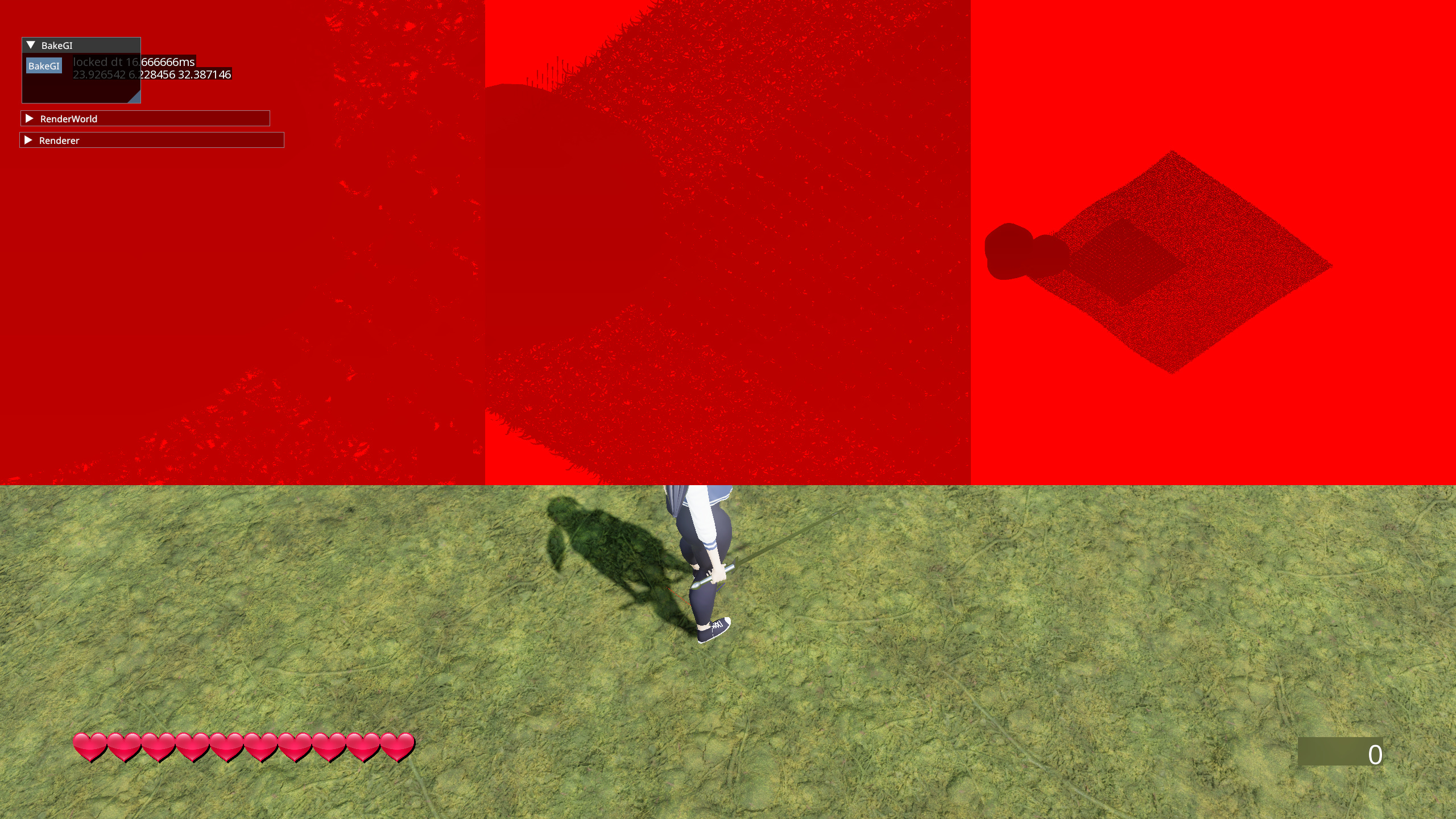
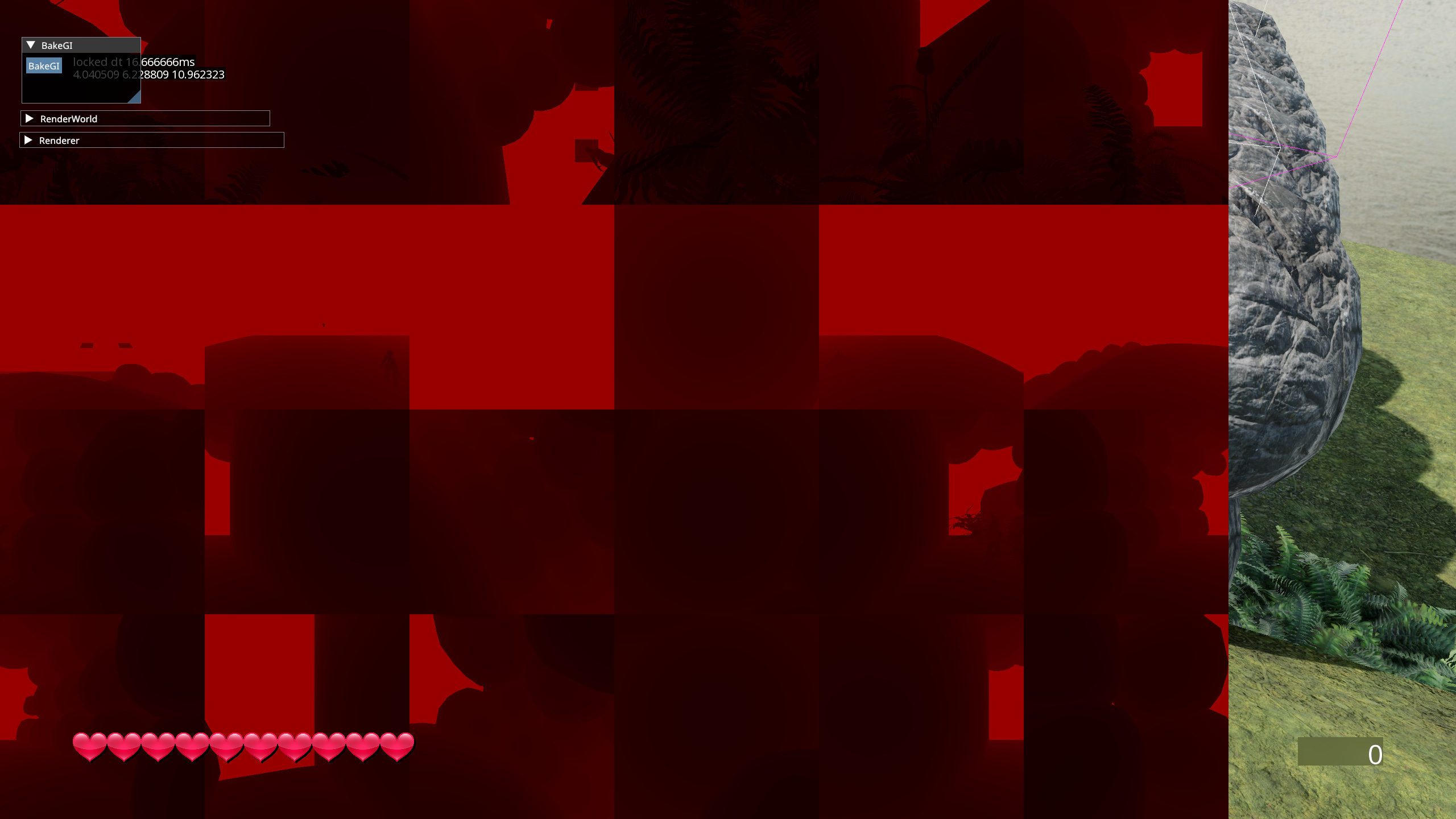
Global Illumination
The crown jewel of my renderer. Many would agree that global illumination might just be the single most important aspect of lighting in a modern game. It’s the magic sauce that really ties everything together and makes the scene feel coherent.
The method I opted for is a limited version of DDGI. The main difference being my GI is pre-computed and doesn’t use Ray Tracing. Other than that it’s pretty much the same technique. Uniform grid of probes being interpolated. Probes themselves are stored as a 2D texture of octahedrally mapped rectangles.

Octahedral mapping is a great way to encode 3D direction vectors into 2D space. It has relatively small error and is computationally cheap. Implementation is the same as DDGI, and doesn’t even require trigonometric functions.
Probes have color and visibility information. Visibility info mostly prevents leaking. It’s not a magic fix but still much better than bare trilinear blend.
Rendering is done with the same renderer as the main view. Scene is drawn 6 times from the probe’s perspective then convoluted into a small 8x8 pixel rect for the color part. Visibility info is 16x16 pixels. Some features are disabled for probe rendering like SSAO, forward pass and other things that shouldn’t show up or take too long.
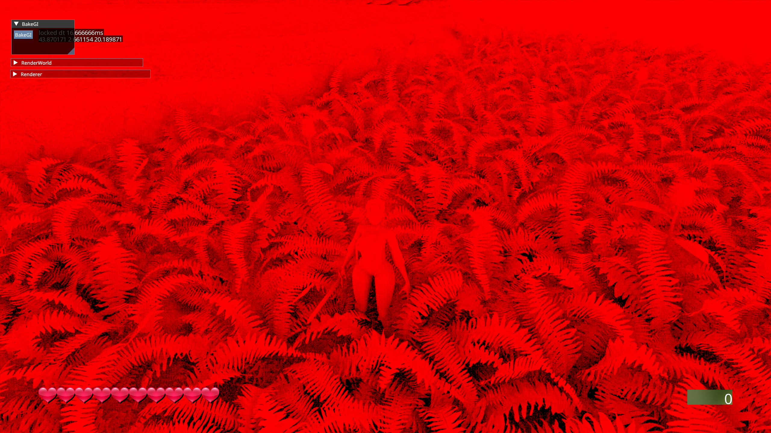
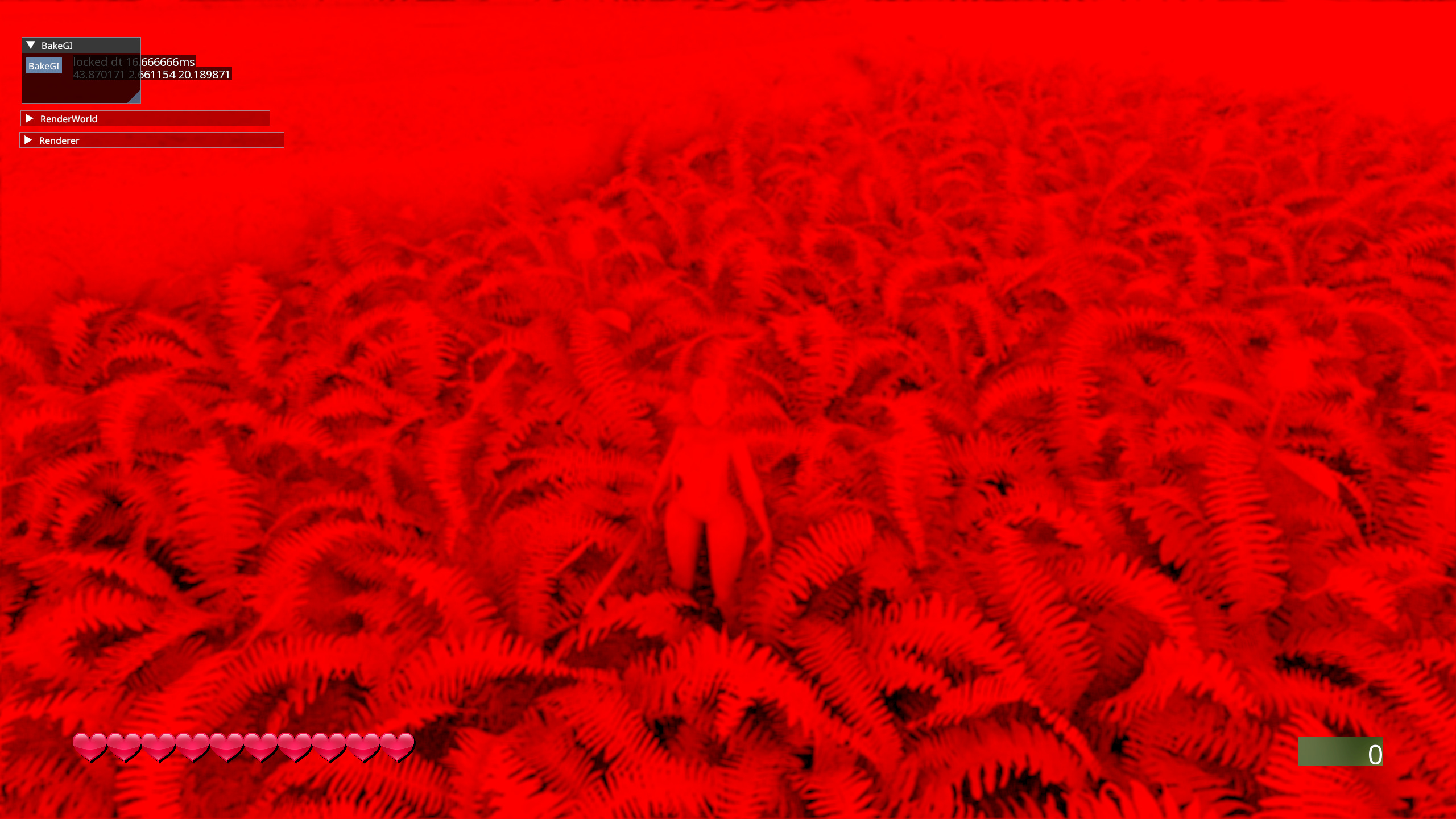
Renderer has 3 modes it can render in:
Default - Used for the main view. All features enabled and all lighting calculations performed.
First Probe - Used for diffuse probes. Limited features are enabled. Shadowed areas are pitch black.
Accumulation Probe - Used for specular probes. Same limitations are in place. Difference being it uses diffuse GI in rendering. So reflections don’t have pitch black shadows in them.
GPU Driven Rendering
GPU Driven Rendering is a term referring to a set of techniques meant to move the load of rendering and rendering adjacent calculations from CPU to GPU. That doesn’t just mean rasterization like always, but also batching, culling, LOD selection, issuing draw calls etc. This helps reduce number of RHI calls significantly, freeing CPU to do other things and letting GPU do what it’s good at - Sickeningly parallel floating point computations.
Bindless
Bindless resources are a feature of all modern RHIs. Primarily used for textures. Meaning the shader provided with such descriptor has access to all textures. All it needs is to be provided with an index. Texture bindings used to be one of the prevailing reasons to split draw calls - not anymore.

Indirect Drawing
Indirect drawing is a method of performing draw calls that allows GPU to decide about if and how they happen. For example:
A regular draw call in Vulkan would look like this:
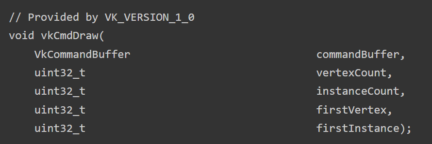
A couple arguments vertexCount, instanceCount, firstVertex, firstInstance. If you wanted to issue multiple draws where those arguments are different you would have to issue this command multiple times. Thus creating a lot of overhead from CPU having to communicate with the driver.
But if you could say, put those arguments into a struct:
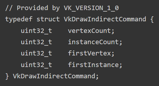
Provide the draw command with an array of those, and store it in GPU memory. Compute shader could write them out. The CPU only needs to record one command for any number of actual draws.
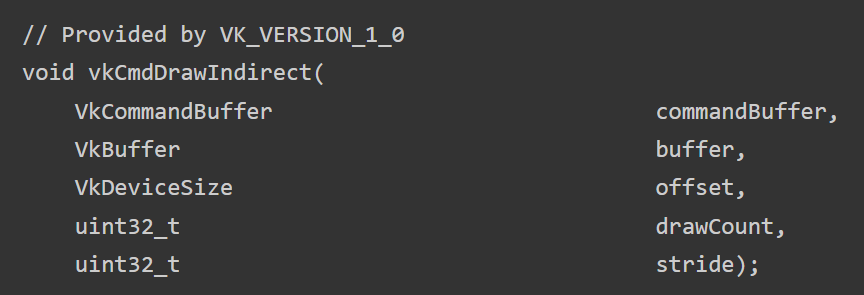
This is the preferred way of issuing draw calls on a modern GPU. Should be utilized if at all possible. But limitations like having to store all vertices in one big buffer could prove prohibitive in some contexts.
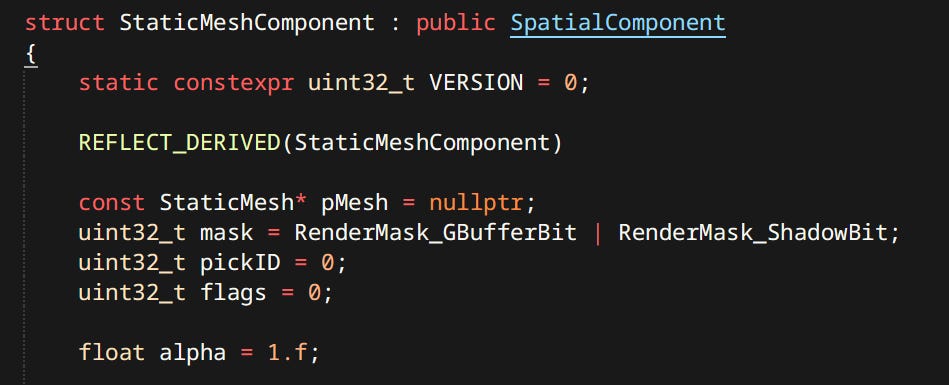
GPU Representation
Because a significant amount of work is offloaded to the GPU many constructs have to be stored in VRAM as well as RAM.
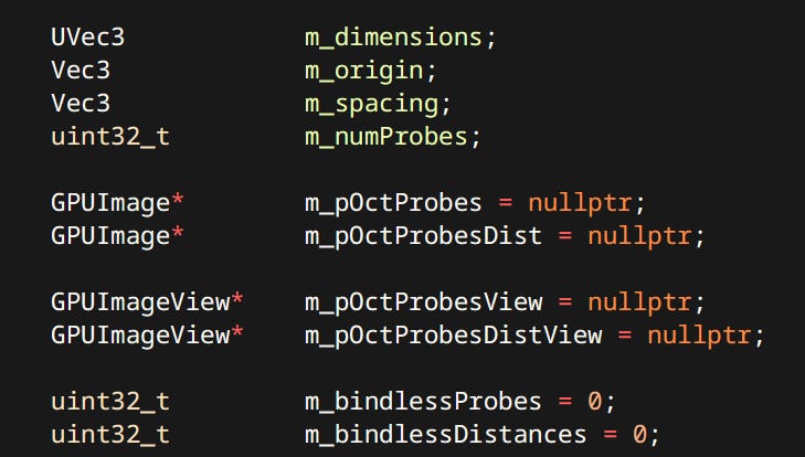
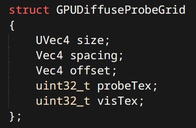
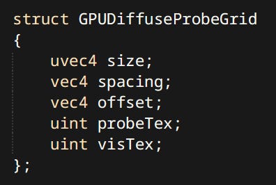
Most of them have a separate version prefixed with GPU. Like the GPUDiffuseProbeGrid or GPUPointLight. Note the use of integers for textures thanks to bindless descriptors. The data is packed and all padding and alignment is taken into account to ensure compatibility with mirrored definition in GLSL.
Mesh Batch Sets
GPU Mesh data is stored in multiple places:
There’s are big global vertex and index buffers storing data for all meshes. There’s also a separate buffer for joint weights.
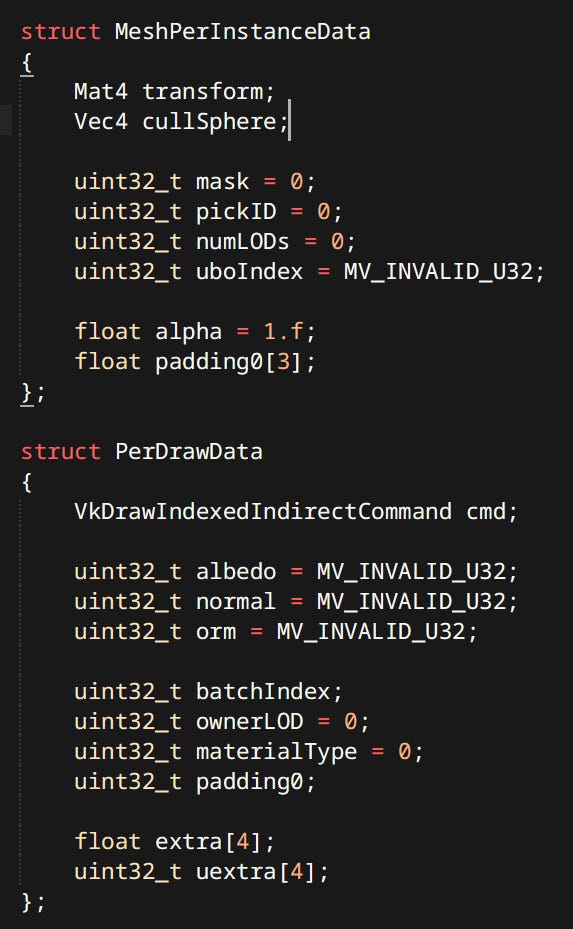
There’s the MeshInstanceSet which holds data for all registered mesh instances in the RenderWorld. Instance contains data relating to the entire mesh (all LODs and all primtives). e.g. transform, cull sphere, pick ID, mask etc.
Finally there’s multiple MeshBatchSets one for every PSO. They contain the draw commands for every Primitive and every LOD.
When meshes are drawn the target pass first issues culling and then any number of draws.
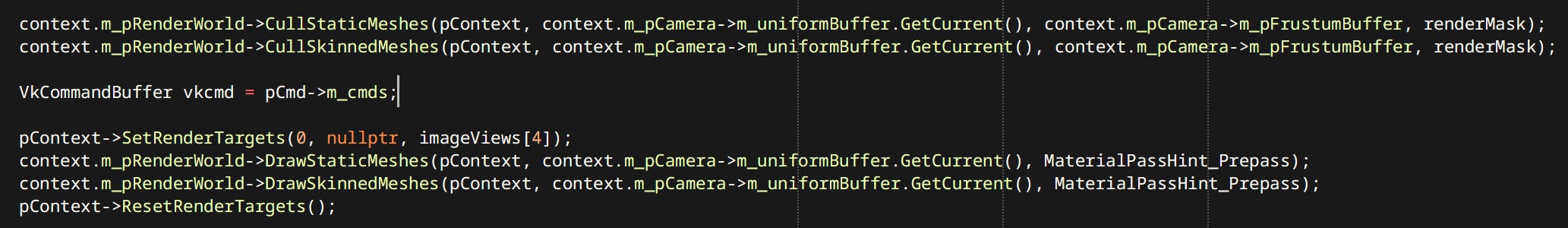
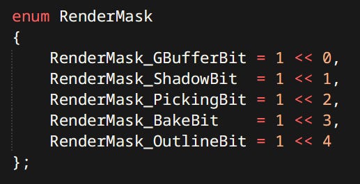
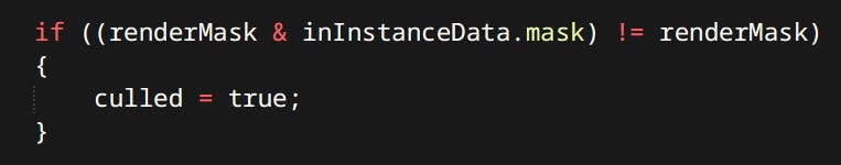
RenderMasks are flags that filter out draws in the cull compute shader. Can determine whether the given mesh can cast shadows, be present in probes, be outlined, etc.
On the subject of batching here’s a couple of stats:
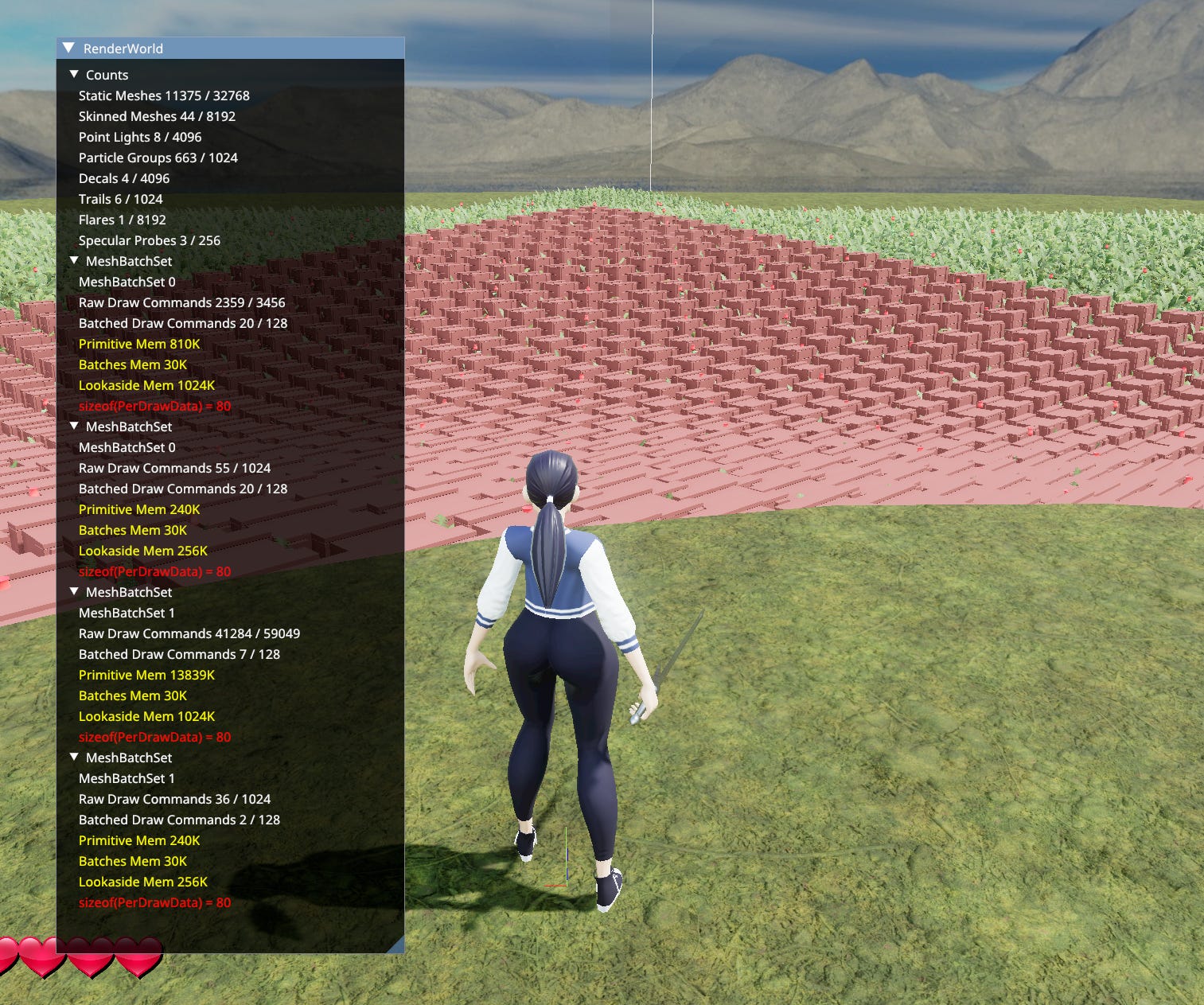
For 11375 Static Meshes and 44 Skinned Meshes - 43734 raw draws are generated. Those are per mesh, per LOD, per primitive. These get culled and batched in a compute shader. Resulting in 49 draw commands across 4 CPU-side draw calls. There’s one CPU draw call per MeshBatchSet. The number of draws is much smaller than the number of meshes because instancing is also used. I’d say that’s a pretty good ratio.
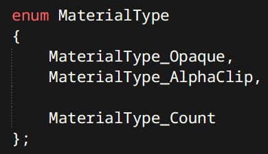
Currently material types are hardcoded.
Room For Improvement
Currently the contents of MeshInstanceSets and MeshBatchSets are uploaded every frame which takes a long time. I should invest in some kind of command buffer like setup where I can change mesh properties without reuploading all that data. There’s a dirty hack for that right now and even that causes a major performance improvement.
Also I’ll probably want to make the material types data-driven at some point.
2D Rendering
2D Rendering is not nearly as interesting or complex as 3D. 2D Renderer can only render one thing: A piece of textured 2D geometry.
Rectangle - Is two triangles with pure white texture.
Sprite - Is two triangles with a chosen texture.
Text - Is multiple rectangles with a font texture which is white and transparent.
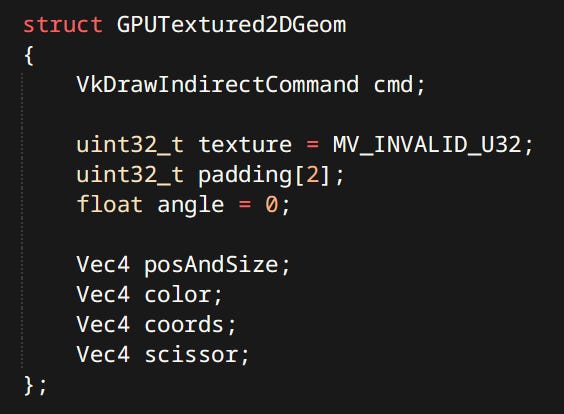
GPUTextured2DGeom is a draw command with additional data. All geoms are gathered together into a GPU buffer and drawn using vkCmdDrawIndirect. They also support scissoring using fragment shader discard. Regular scissoring is not possible since it cannot be changed between indirect draws.
Fonts
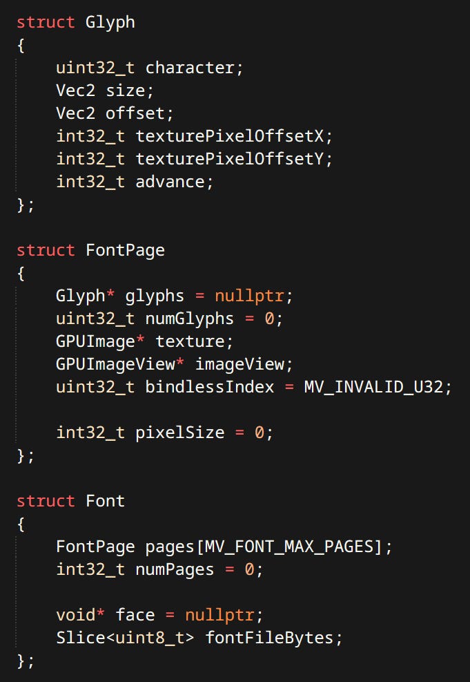
Only particularly interesting part of 2D rendering is text. I use FreeType library. It rasterizes beautiful and sharp glyphs. Font (formally called typeface) is a collection of pages (formally called fonts). A Page is a collection of Glyphs in a particular size. Pages are rasterized on-demand.
When user code wants to draw some text two main functions are used.
FontMeasureString - Returns the size of the string for a given font, for a given size.
FontCreateVertexDataFromString - Fills an array of vertices with rectangles required to render the given string (for a given font, for a given size). Complete with UVs. This function also returns the size of the drawn string. One or the other is used depending on whether the size needs to be known a priori.

The Gameplay Structure
The place where all the systems come together. The ultimate integration hell location. Unreal calls it the ‘Gameplay Framework’. I didn’t know what to call it - so I just called it ‘Gameplay’. The Gameplay concerns itself with the world, entities how they are structured and how they interact with each other.
My Entity Model is inspired by Bobby Anguelov’s Kruger Entity Model. Which itself is a twist on Unreal’s Actor Component Model.
Entities, Components and Polymorphism
Entities are things that exist in the game world. Characters, pickups, rocks, all the things. In this case an entity is a bag of components - a very popular approach. What makes this system similar to Unreal’s is that entities can also be inherited types.
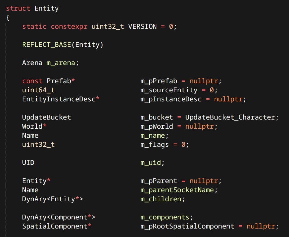
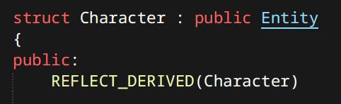
Inheritance is exclusively used for the purpose of polymorphism. There are no family trees of entities. The reason why both components and inheritance are present is quite simple - legacy.
At first I did the simplest thing I could think of, which was a polymorphic entity. Inheritance happens to be my preferred way of achieving polymorphic behavior in C++. As the amount of functionality, and thus complexity increased, it had to be managed somehow. Components are a popular and well liked method of doing just that. Given that my code already heavily favored composition over inheritance it wasn’t a major cost to formalize the exitance of components.
As of now I’m considering whether it’s worth the effort to consolidate all entity types into one generic Entity type and eliminate the inheritance - we’ll see.
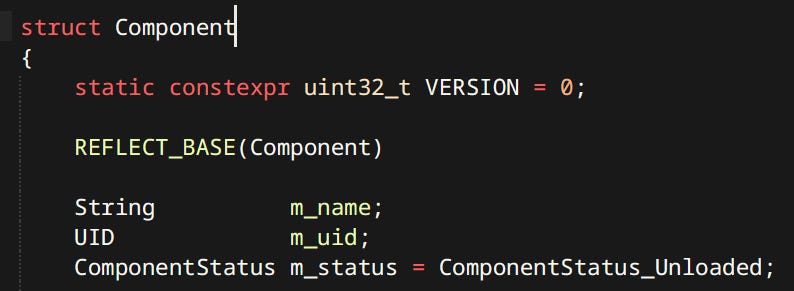
Components exist in two variants: Spatial and Non-Spatial.
Spatial Components - Are the ones that participate in transform hierarchy. Meaning it’s not the stored data that makes it spatial. e.g. Ragdoll Component is not considered spatial even though ragdolls obviously occupy 3D space. It’s whether they can be attached to other components or have other components attached to them. Skinned Mesh is a spatial component and can have other things attached to it. like sword being held in hand.
Non-Spatial Components - Store data that has no bearing on component transforms. Usually used for pure logic like. Anim Graphs, Ragdolls, AI Knowledge etc.
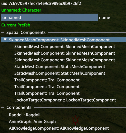
Character is an example of entity whose structure is defined in code as opposed to data loaded from disk. (That’s why components only have their default names)
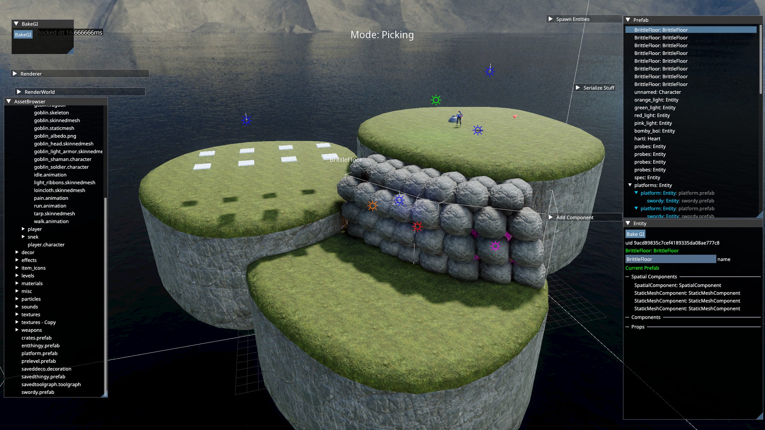
There exists a basic prefab system. Since a prefab is just a ‘bag of entities’, levels and prefabs are both the same thing. Prefabs can also contain other prefabs. It’s more of a serialization feature rather than anything having to do with gameplay architecture.
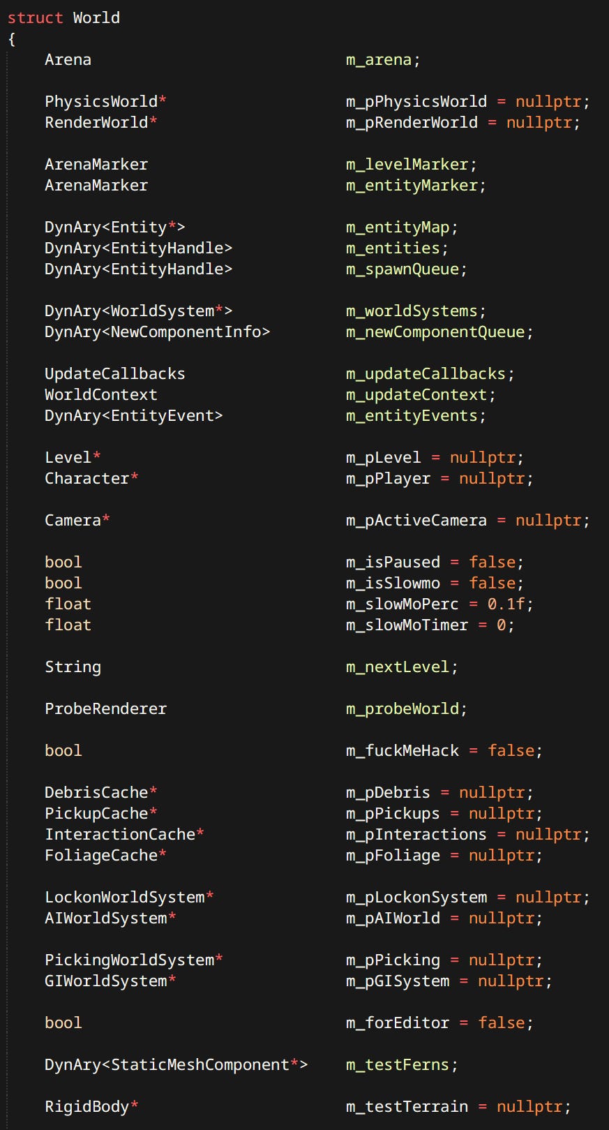
The World
The World is a place where entities live. In the game there’s only ever one world, but in the editor each individual Workspace has it’s own world with it’s own entities. A level for example is just a bunch of entities that can be loaded or destroyed at any time. This is where the meat of the simulation happens.
If something doesn’t have a good reason to exist somewhere else, it lands in the world. Various test entities and hacks are present at all times.
World Systems
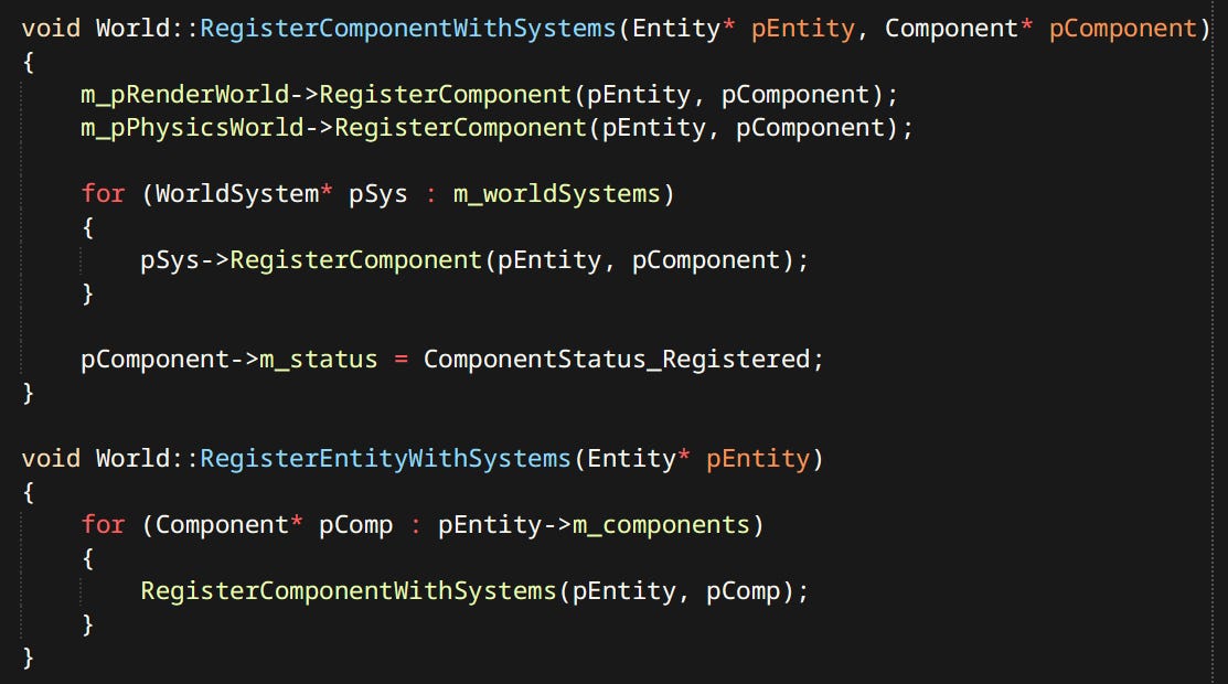
The other piece of the puzzle is ‘World Systems’ these are directly stolen from inspired by Bobby Anguelov’s idea. Every game, without exception, sometimes wants to look at components of type, independently from their belonging to entities. This is often approximated in Unity with various queries. Many AAA engines have global singletons that components register themselves into (fun fact: Ubisoft had such a problem with global singletons that they needed to create something called ‘singleton storers’ to control initialization order between them). Well here this idea is formalized into World Systems.
World System is a place for arbitrary operations that gets notified when individual components get registered and unregistered from the simulation.
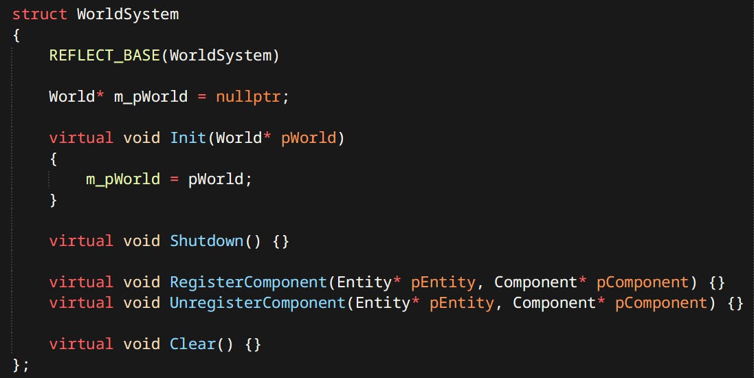
Unlike ECS the world systems are not only allowed but expected to have state. As much as they want in fact. RenderWorld is actually an example of what World Systems do.
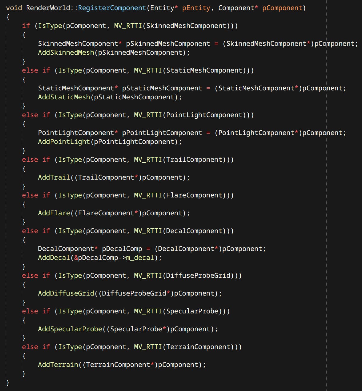
Upon registration RenderWorld batches and packs component data as is needed by the renderer.
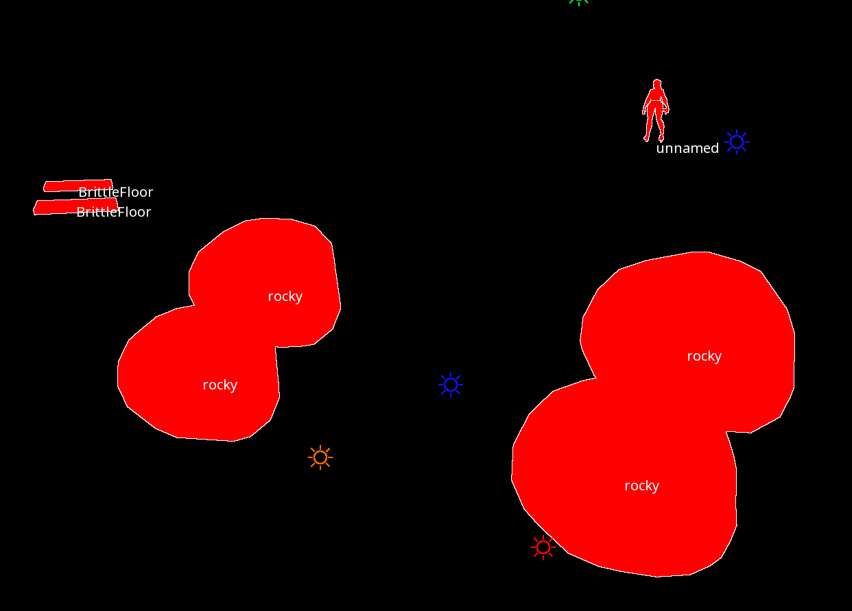
There are systems that serve gameplay like LockonWorldSystem which handles locking on to enemies, but there are also world systems that serve tooling like PickingWorldSystem which handles clicking on entities to select them or GIWorldSystem which gathers all probe components and bakes indirect lighting on demand.
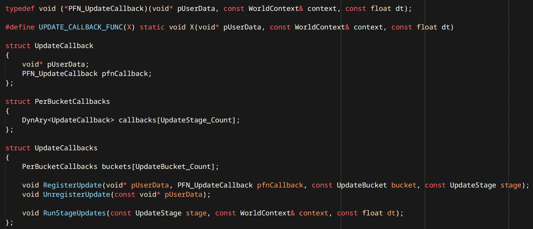
Updates
Running updates is a surprisingly involved problem. We want to:
Update entities and systems that want to update
Skip things that don’t need to update
Update entities and systems in relation to the stage in frame
Update entities in relation to each other
To address this problem I have opted for a solution similar to the ‘Update Schedulers’ you can find in many engines. Only mine is much simpler.
Updating has 2 dimensions in my engine. First there are update stages:
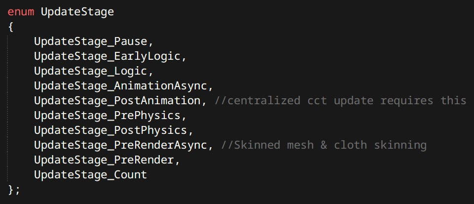
Which define where in the frame the update is supposed to happen. Update stages are named after most important things that happen at that time. For example when we want to change the pose of a ragdoll we have to do it after animation is update but before physics is run. So we should put it in PostAnimation or PrePhysics. This is the main way of ordering systems.
Secondly there are ‘buckets’:
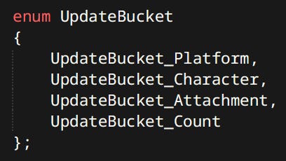
Buckets are an idea I got from Jason Gregory’s Game Engine Architecture. The go to resource for engine programming knowledge. I have to say this book was instrumental in much of my learning and many architectural decisions.
Buckets serve to order entity updates relative to each other. Platform, Character and Attachment are good example.
First we want the platform to move, it not being dependent on anything.
Then with the current platform information we can update a character and move it appropriately.
Then after the character is in it’s final position. The gun on it’s back has all the up-to-date data to run it’s own update.
It’s a much simpler solution than resolving explicit dependency graphs like the ones found in Unreal or CryEngine. Also it was clearly good enough to ship Uncharted 4 and The Last of Us Part II, so I think it’s safe to say it’s gonna be good enough for me :)
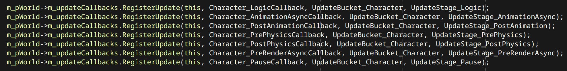
Each Entity or World System can register updates as needed:
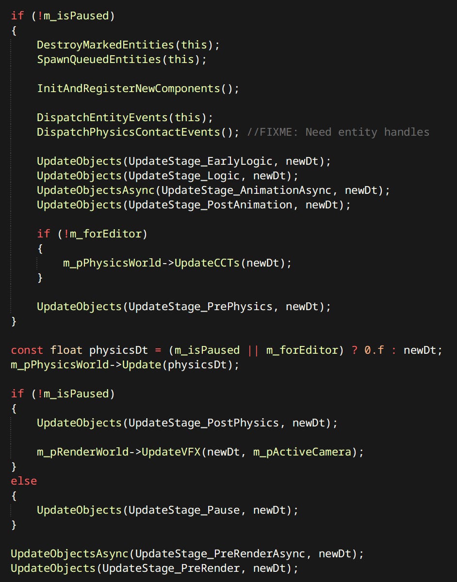
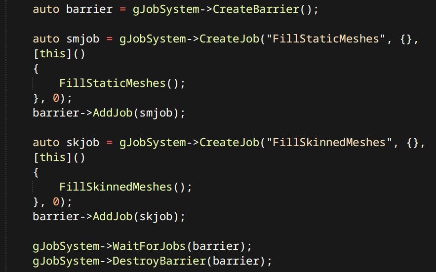
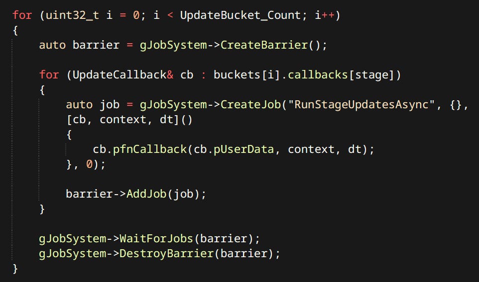
Running updates in parallel is quite trivial with the use of the Job System:
Characters
Characters are by far the most complex and gameplay relevant entities I have. Trying to figure out the way to handle them has been one of the hardest problems I tackled. The solution in the end is quite simple, even embarrassingly so.
HFSMs to The Rescue
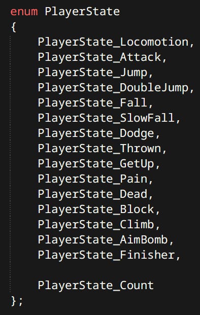
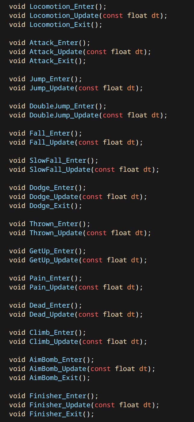
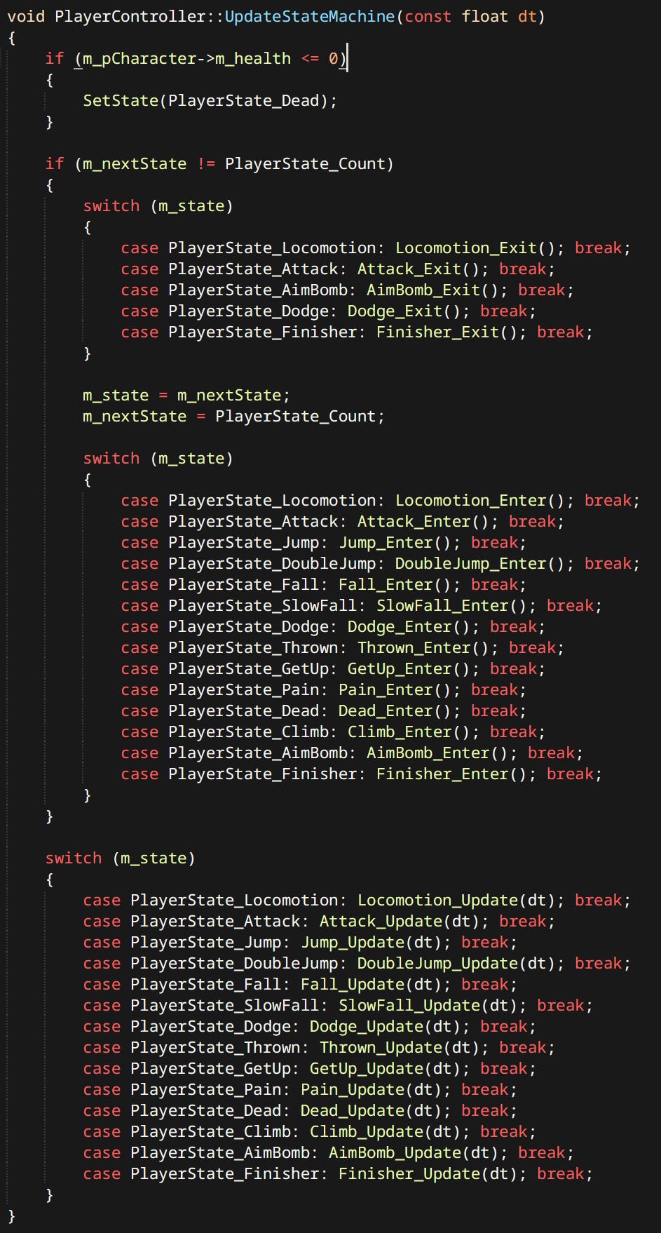
Each character has a ‘Controller’. Controller is just a simple hardcoded state machine. States are defined by enums and functions.
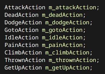
Each state can constitute of one or more ‘Actions’. Actions are discrete things that characters can do. Like Attack, Dodge, Go To etc. Many Actions are shared between player and the enemies.
Using actions is extremely simple:

For the player controller each state is usually just one action. Since actions are coordinated in the brain of the human playing the game.
For the enemies each state is considered a behavior:
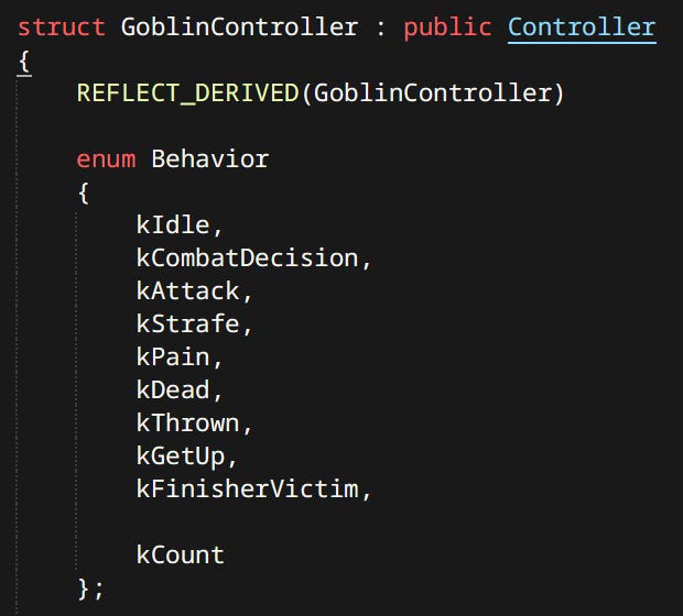
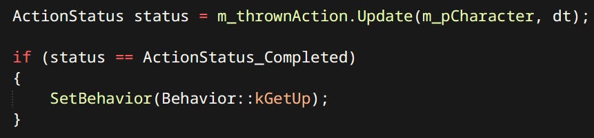
A behavior can correspond to one or more actions. Some behaviors are simple like kDead. Others like kAttack are mini state machines of their own. If Goblin is close enough to perform attack it invokes the Attack Action. If not it uses the Go To Action to get close enough.
Currently actions are pretty bad at being their own state machines. I’d like to modify the system to make composing of state machines easier.
The rest of gameplay is not going to be covered here since this article is meant to be more about tech side of things. Besides things like combat are good topics for posts of their own.
Tools
The application has an embedded editor. I can switch to it by pressing F10 at any time. The editor is a set of Workspaces.
Each Workspace allows viewing or editing a specific type of asset. Most workspaces can only serve as viewers.
The assets can be re-compiled and reloaded from console. The respective workspaces have callbacks to handle reloading. Tools are vary bare bones. I tend to only add functionality as I need it. It’s been working well for me so far, since it’s only me dealing with these.
Conclusion
There are great many things to improve, and even more still to do. I look forward to all of it. Working on this game is my favorite thing to do. Expect more posts in the future.
Special Thanks
To Casey Muratori for starting Handmade Hero and showing me that programming can be enjoyable again.
To Jason Gregory for writing the ultimate Game Engine Bible and shedding the light on real AAA quality engineering.
To Bobby Anguelov for covering important topics that don’t get enough attention, in his live streams.
To Jorrit Rouwe for deciding to Open-Source his awesome physics engine. It’s not just useful as a library, I learned a lot from studying it’s source code.
To my friend Christopher for giving feedback on early versions of this article.
Most people mentioned here don’t know me but I feel thankful nonetheless. Resources and links are provided when mentioned for the first time in the body of the text.